Powertrax 1540 User Manual
Page 7
7
Mark the carrier and bearing cap on the ring gear side with one
punch mark and on the other side with two marks (Figure 2).
The caps are not interchangeable! Also mark each bearing ad-
juster directly under the lock with this same mark to note its side
and rotational position. This mark is very important to correct
re-assembly!
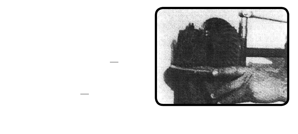
4. Remove the adjuster locks. (See Figure 3). Be sure
that each adjuster is marked at the lock with the correct number
of punch marks for each side. The adjusters are not interchange-
able after they are marked for position! (In general, the adjuster
locks themselves are interchangeable.)
5. Remove the bearing caps (Figure 3).
6. Slide (tap) the adjuster up and out and remove the
bearing race on the ring gear side first and put a very small grind
mark on the outside of the race to mark it. Scraping it on a ce-
ment floor also works, or you can use a tag. Be sure that you can
identify it for proper re-assembly on the correct side!
Figure 3
Remove bearing caps and adjuster locks