2 imfd daisy chain – PLX Devices DM-100 OBDII User Manual
Page 10
Users Guide: iMFD User Guide
Version 1.0 Jan 1, 2008
www.plxdevices.com
(408)745-7591
10
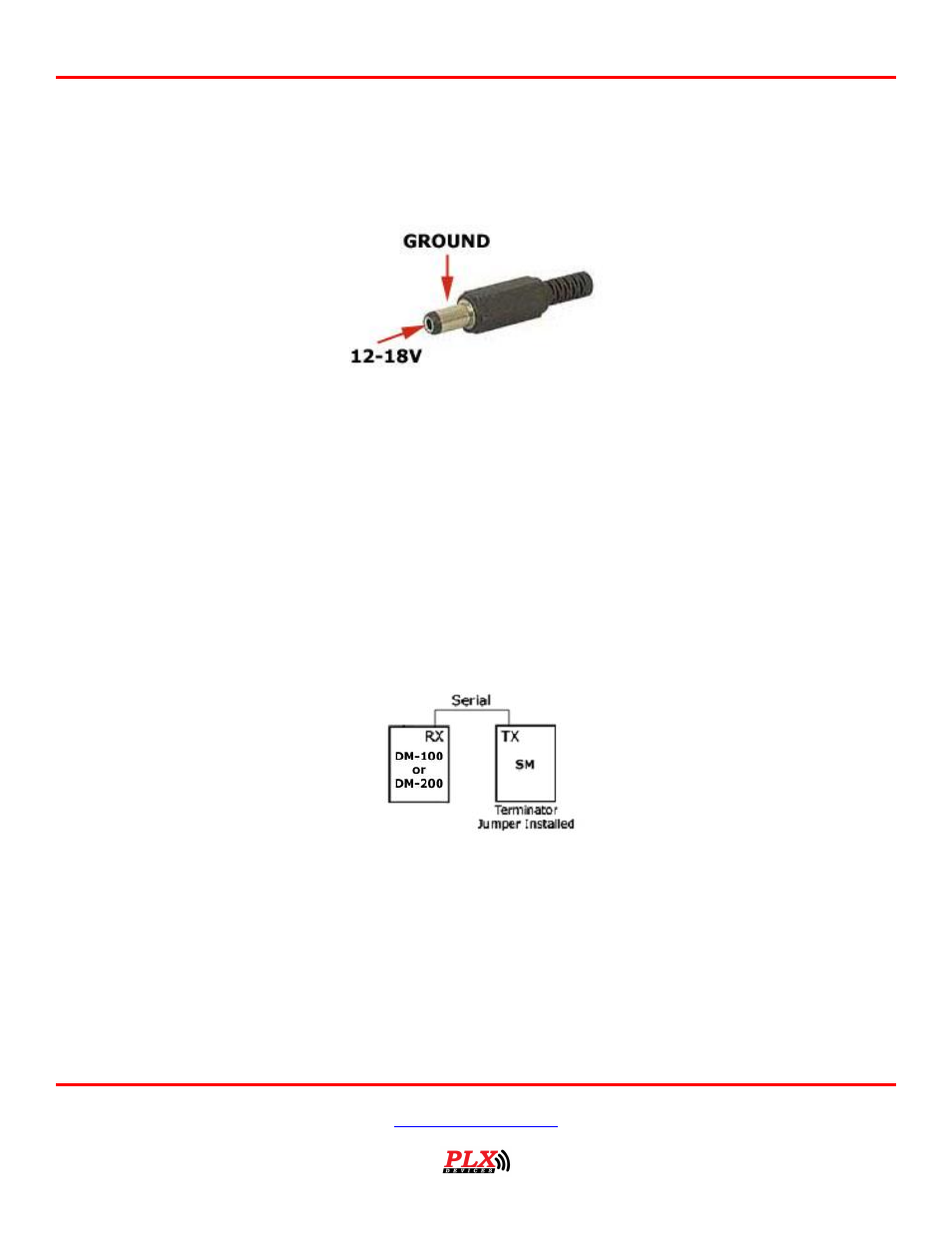
The DM-100 OBDII accepts 12-18V DC for power. Connect the negative wire (black) to your vehicle’s
ground. This is usually the negative terminal of your automobile’s battery. Connect the positive wire (red)
to your vehicle’s ignition power. This power is only supplied when your key is turned passed a specific
position and is off when your key is removed. Your power connection must be capable of supplying at least
1 amp of current. A 5 Amp fuse is recommended for safety. Plug the 2.1mm power plug to the DM-100
OBDII main control box where indicated “POWER.”
The unit is working properly when the OLED screen turns on within 10 seconds. If your gauge does not
turn on, check your power connections and gauge connections.
3.2 iMFD Daisy Chain
The iMFD architecture allows you to connect up to 32 Display Modules and 32 Sensors in a daisy chain
format. Please keep in mind that the DM-100 OBDII has 4 SMs built-in. The 4 built-in SMs can be
programmed up to 26 different combinations. See section (3.3).
Basic Setup:
The most basic setup is to have one DM-100 and one Sensor Module connected in the iMFD chain. Make
sure that the sensor module has the termination jumper INSTALLED. Use the 1ft serial cable provided to
make the connection. Again please note, your DM-100 OBDII Already has 4 built-in SMs.
Multiple Sensor Setup:
If you have more sensor modules, simply connect them in between the DM-100 and the Sensor Module.
Make sure that any subsequent sensor modules added to the iMFD daisy chain MUST have the termination
jumper REMOVED. Use the 1ft serial cable provided to make the connections.