Stx-series — maintenance – Multiquip STX55Y6 User Manual
Page 37
STX-SERIES • RIDE-ON POWER TROWEL — OPERATION MANUAL — REV. #0 (03/15/06) — PAGE 37
/02) — PAGE 37
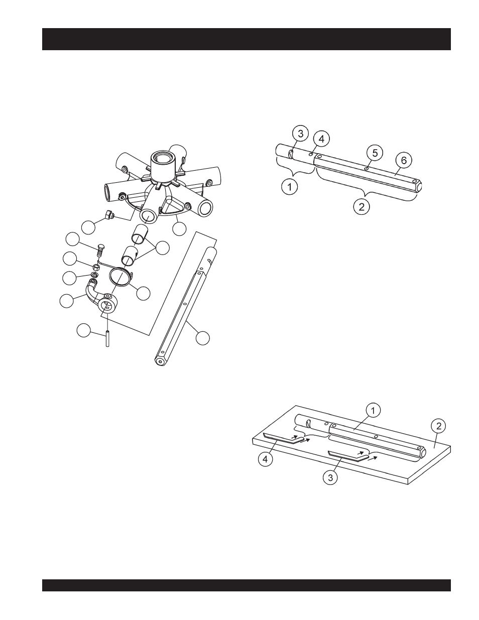
3. Should the trowel arm inserts (bronze bushing ) (item 2 Fig.
34) come out with the trowel arm, remove the 2-piece
bushing from the trowel arm and set aside in a safe place. If
the bushing is retained inside the spider plate, carefully
remove the bushing.
4. Examine the 2-piece bronze trowel arm bushing insert (Fig-
ure 34), clean if necessary. Replace bushing if out-of-round
or worn.
Figure 34. Bronze Bushings
STX-SERIES — MAINTENANCE
1
Spider Plate
2
2-Piece Bushing
3
Hex Head Screw
4
Hex Head Screw (Rounded)
5
Hex Jam Nut
6
Lock Washer
7
Trowel Arm Lever
8
Roll Pin
9
Trowel Arm
10
Arm Return Spring
5
4
6
2
1
3
7
8
9
10
1. Use a thick steel plate, granite slab or any surface which is
true
and
flat
, to check all
six sides
of each trowel arm for
flatness.
2. Check each of the six sides of the trowel arm (hex section).
A feeler gauge of .004" (0.10 mm) should not pass between
the flat of the trowel arm and the test surface along its length
on the test surface. (Figure 36, Item 3) .
Figure 36. Checking Trowel Arm Flatness
Checking Trowel Arm Straightness
Trowel arms can be damaged by rough handling, (such as dropping
the trowel on the pad), or by striking exposed plumbing, forms, or
rebar while in operation. A bent trowel arm will not allow the trowel
to operate in a smooth fluid rotation. If bent trowel arms are suspect,
check for flatness as follows, refer to Figures 35 and 36:
1
Trowel Arm
2
Flat Test Surface
3
Feeler Gauge (.004 in. / 0.10 mm)
4
Feeler Gauge (.005 in. / 0.127 mm))
1
Trowel Arm Round Shaft Section
2
Trowel Arm Hexagonal (Hex) Shaft Section
3
Lever Mounting Slot (Left Arm Shown)
4
Roll Pin Hole
5
Blade Attachment Bolt Hole (One of Three)
6
Flat of Hexagonal Shaft (Top of Arm)
Figure 35. Trowel Arm