Htx-yanmar diesel — maintenance – Multiquip HTX44Y5 User Manual
Page 37
HTX-YANMAR DIESEL • RIDE-ON POWER TROWEL — OPERATION MANUAL — REV. #0 (07/06/06) — PAGE 37
/02) — PAGE 37
HTX-YANMAR DIESEL — MAINTENANCE
Changing A Blade
It is recommended that all the blades on the entire machine are
changed at the same time. If only one or some of the blades are
changed at one time, the machine will not finish concrete
consistently and the machine may wobble or bounce.
1.
Place the machine on a flat, level surface. Adjust the blade
pitch control to make the blades as flat as possible. Note
the blade orientation on the trowel arm. This is important
for ride-on trowels as the two sets of blades counter-rotate.
Lift the machine up, placing blocks under the main guard
ring to support it.
2.
Remove the bolts and lock washers on the trowel arm, and
then remove the blade. (Access is easier if the steps are
removed.)
3.
Scrape all concrete and debris from the trowel arm. This is
important to properly seat the new blade.
4.
Install the new blade, maintaining the proper orientation
for direction of rotation.
5.
Affix the bolts and lock washers.
6.
Torque to 9 ft. lbs.
7.
Repeat steps 2-6 for all remaining blades.
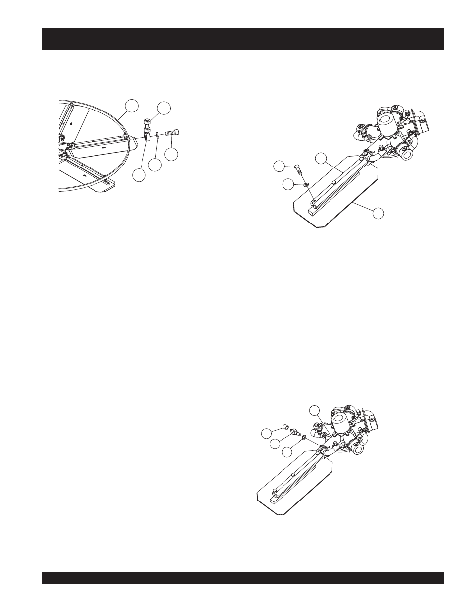
Stabilizer Ring Removal
1. To remove the outer stabilizer ring, (Figure 32), remove the
six bolts at the end of each spider arm.
Figure 32. Stabilizer Ring
2. Examine stabilizer ring for out of round or bends. If ring is
damaged, replace ring. If ring is found to be correct with no
damage, set aside.
Trowel Arm Removal
1. Each trowel arm is held in place at the spider plate by a hex
head bolt (with zerk grease fitting). Remove the hex head
bolt/zerk grease fitting from the spider plate. (Figure 33)
2. Remove the trowel arm from the spider plate.
Figure 34. Removing
Zerk Grease Fitting
Trowel Blade Removal
1. Remove the trowel blades from the trowel arm by removing
the three hex head bolts, (Figure 33) from the trowel arm. Set
blades aside.
Figure 33. Trowel Blade Removal
2.
Wire brush
any build-up of concrete from all six sides of the
trowel arm. Repeat for the remaining arms.
1.
Hex Cap Screw
2.
Lock Washer
3.
Rod End
4.
Hex Nut
5.
Stabilizer Ring
1.
Hex Cap Screw
2.
Lock Washer
3.
Arm
4.
Blade
2
5
4
3
1
2
3
4
1
2
3
4
1
1.
Spider Plate
2.
Cap
3.
Hex Head Bolt (Zerk Fitting)
4.
Star Washer