Jtn ride-on trowel, Controls and indicators – Multiquip JTN User Manual
Page 20
PAGE 20 — JTN RIDE-ON TROWEL— OPERATION & PARTS MANUAL — REV. #5 (08/03/067)
JTN RIDE-ON TROWEL
—
CONTROLS AND INDICATORS
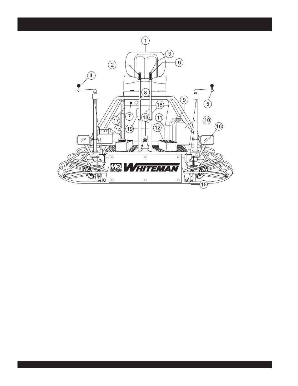
Figure 5. JTN Controls and Indicators (Front)
1.
Seat – Place for operator to sit. Engine will not start unless
operator is seated. Seat is adjustable, fore and aft for
operator comfort.
2.
Steering Control Lever (right-side) -Allows the unit to
move in either a forward, reverse left or right direction.
3.
Retardant Spray Control Button – When pressed allows
retardant spray to flow through the spray nozzle located at
the front of the machine.
4.
Twin Pitch Control – Adjusts the blade pitch for right side
of the trowel. Turn the crank as marked on its top surface to
increase or decrease blade pitch.
5.
Twin Pitch Control – Adjusts the blade pitch for left side
of the trowel. Turn the crank as marked on its top surface to
increase or decrease blade pitch.
6.
Steering Control Lever (left-side) -Allows the unit to
move in either a forward, reverse left or right direction.
7.
Light Switch – When activated, turns on four halogen
lights. Lights offer better visibility when working indoors.
8.
Ignition Switch – With key inserted turn clockwise to start
engine.
9.
Fuel Gauge/Filler Cap - Indicates the amount of fuel in
the fuel tank. Remove this cap to add fuel.
10. Fuel Tank - Holds 2.2 gallons of unleaded gasoline.
11. Spare Belt Carrier - Contains 2 spare belts. Belts are used
on the drive pulley.
12. Left Foot Riser – Operator foot rest pedal.
13. Spray Nozzle – Spray nozzle for retardant.
14. Right Foot Pedal – Controls blade speed. Slow blade
speed is accomplished by slightly depressing the foot pedal.
Maximum blade speed is accomplished by fully depressing
the foot pedal.
15. EZ- Mover Boss – Front -side insertion point for EZ Mover.
Used when the transporting of the trowel is required.
16. Lights – Four 12 volt halogen lights are provided with this
unit.
17. Hour Meter - Indicates number of hours machine has been
in use or hours engine was run.
18. Dip Stick- Access hole provided to check engine oil
through this cutout.
19. Spark Plug- Access the spark plug through this cutout.