Memmert PM 200 Self Drying Vacuumpump (Generation 2003) User Manual
Page 5
nents before servicing.
2.) Ensure that the service personnel
is not subject to a health hazard.
Apply the safety and protection
measures that are necessary for
the medium that has been handled
by the pump (example: the use of
protective gloves).
3.) Ensure that discarded parts and
materials are safely and correctly
disposed of.
Ī Use only original KNF replacement
parts.
Required tools and material:
½ Service Set (see section 7)
½ Philips-head screwdriver No. 2.
Change the structured diaphragms and
valve plates/sealings in the following
sequence:
a.) Preparatory steps
b.) Remove pump heads
c.) Change structured diaphragms
d.) Change valve plates/sealings
e.) Refit pump heads
f.) Final steps.
̈ The postion numbers in the fol-
lowing text refer to fig. 2.
a.) Preparatory Steps
ᕡ Shut down system (see section 4.2)
including disconnecting the pump
from the power source (pull out
plug of electrical supply unit).
ᕢ Remove tubing from the inlet and
outlet connectors of the pump.
b.) Removing the pump heads
³ On the pneumatic head connec-
tions, loosen one of the union nuts
by hand. Then slightly loosen the
angle-fitting in the pump head by
turning it anticlockwise, so that the
connecting tube can be pulled out.
· Loosen the outer screws ቢ on
each pump head.
» Carefully remove both pump heads
(top plate
ብ, head plate ቦ and
intermediate plate
ቨ).
Ī
The soleonid valve of the
drying system remains fitted
in this situation.
c.) Change structured diaphragms
ᕡ Push down one structured dia-
phragm
ቪ until other diaphragm is
pushed upwards to its highest
position.
ᕢ Carefully unscrew the higher
strucutred diaphragm anti-clock
wise using both hands.
ᕣ Replace all spacers ቫ/ቭ onto the
screw thread of the new structu-
red diaphragm (same number and
order)
¿ Screw in the new structured dia-
phragm
ቪ and tighten it by hand;
you do not need any tool.
´ Change the second structured dia-
phragm as described above (step
³ to ¿) for the first.
̈ Changing the two diaphragms one
after the other ensures that the
same number of diaphragm spa-
cers are refitted as were removed.
This is essential to maintain the
pneumatic performance of the
pump.
d.) Change valve plates/sealings
ᕡ Unscrew the three screws ባ in
the top plate
ብ of one pump head.
ᕢ Carefully remove top plate ብ and
head plate
ቦ from intermediate
plate
ቨ; exposing the valve pla-
tes/sealings
ቧ.
ᕣ Remove old valve plates/sealings
ቧ.
¿ If there should be deposits in the
recesses in the intermediate plate
ቨ, clean them until the deposits
have been completly removed.
´ Insert new valve plates/sealings
ቧ in the recesses in the interme-
diate plate
ቨ (upper and lower
sides of the valve plates/sealings
are identical).
² Carry out the steps ᕡ to ᕥ for the
PM 1633-842.3-3.00 e 11/05
4
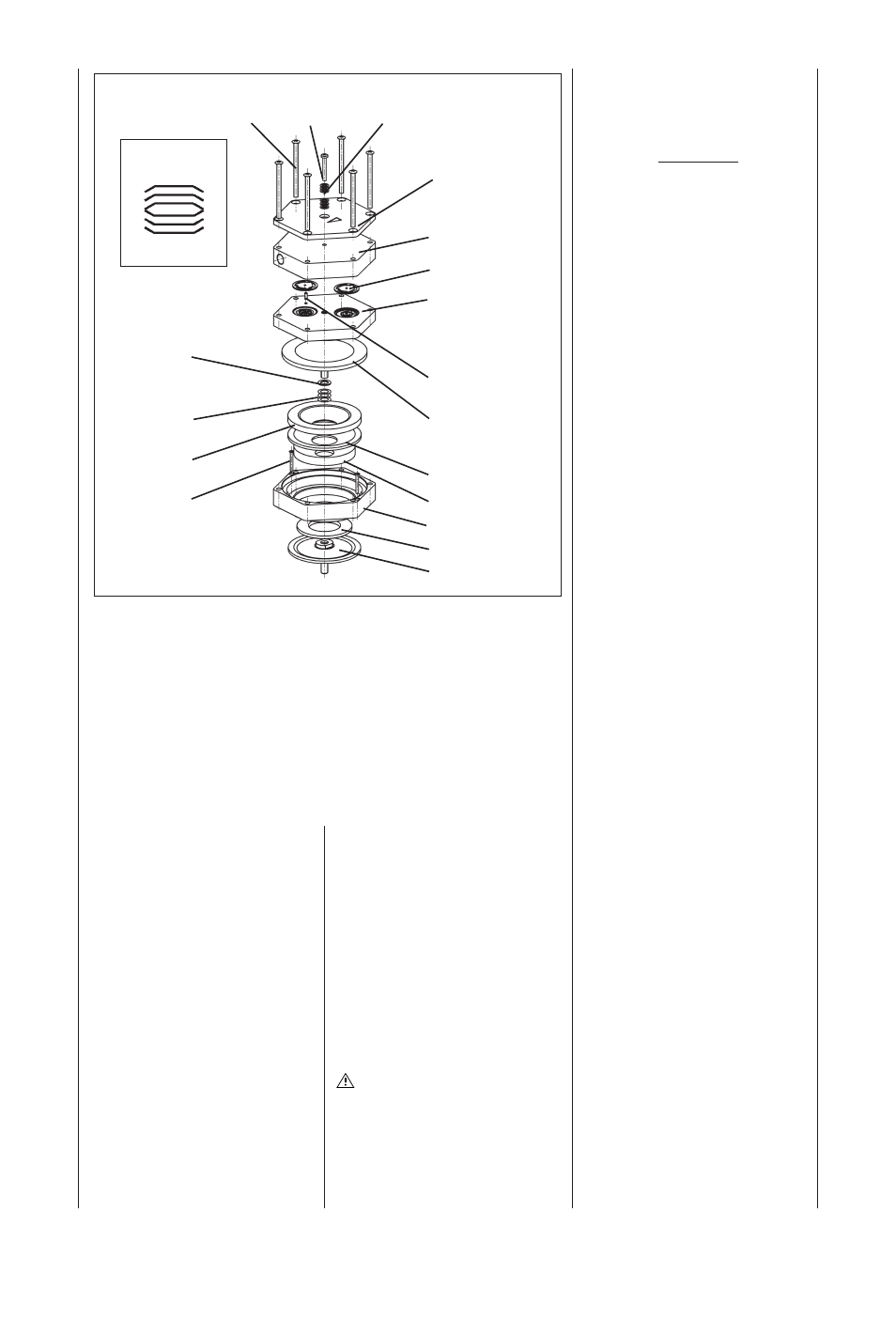
Specification
ቢ
Screw (12x)
ባ
Screw (3x)
ቤ
Disk spring
ብ
Top plate
ቦ
Head plate
ቧ
Valve plate/sealing
ቨ
Intermediate plate
ቩ
Guide pin
ቪ
Structured diaphragm
ቫ
Spacer (thick)
ቭ
Spacer (thin)
ቮ
Dampening ring A
ቯ
Screw
ተ
Dampening felt
ቱ
Dampening ring B
ቲ
Adapter
ታ
Dampening ring C
ቴ
Dampening
diaphragm
ቢ ባ ቤ
ብ
ቦ
ቧ
ቨ
ቩ
ቪ
ተ
ቱ
ቲ
ታ
ቴ
ቫ
ቭ
ቮ
ቯ
Orientation of disk
springs
ቤ
Fig. 2: Pump head for N 842.3_ (exploded drawing, symbolic)
Pump N 842_ has a round shape of head