Induro DM BallHead User Manual
Dm-series ballheads, Operating instruction, The dm series parts diagram
OPERATING INSTRUCTION
DM-Series BallHeads
Thank you for making Induro your choice for professional photographic gear.
Before using this equipment please read these instructions for proper use and
the best performance.
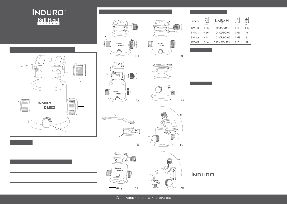
The DM Series Parts Diagram
The INDURO DM-Series ball heads are black anodized machined aluminum
and offer three operating knobs. Drag is manually adjusted and locked, along
with independent panning. They include a sliding quick release plate with
secondary safety lock system.
Prefix
1 and 2 Digit
st
nd
Locking System
Balanced for Series
DM = Manual Drag Control
0 = Series 0
01 = Series 0 & 1
12 = Series 1 & 2
23 = Series 2 & 3
34 = Series 3 & 4
The dm series operating methods
Table of DM Series
Features:
Identifying ball head model numbers
Your Induro DM Ball head has been designed for years of maintenance free use. Please follow the
guidelines below to ensure the best performance, reliability and durability expected from Induro Gear.
1.Do not exceed the maximum specified load capacity (see product specification chart) !
2.Always ensure that the ball lock is tightly engaged before mounting a camera onto the head !
3.Do not use the ball head below temperatures of -4°F or above +158°F (-20°C / +70°C) !
4.Always clean and dry the ball head after it has been exposed to wet, dusty, sandy or salty conditions.
Your DM ball head is not recommended for use in salt water. Clean the ball head with a mild soap and
soft cloth. Remove any dust, dirt or sand from the ball, ball lock lever and threads, and all moving
parts. !
5.Use the correct series ball head with the recommend series tripod to avoid unequal balancing
issues. !
6.Do not over tighten locking levers, as this could damage the ball head locking mechanism. !
Before using your DM Ball head, make sure you are using the correct size ball head for the tripod series
and camera weight intended. Always engage any safety locks on the support head to prevent any
accidental dismounting.
1.Quick Release Plate: (See figure 2) The DM-Series incorporates a quick release plate system. It
offers a quick method of mounting or releasing a camera or equipment from the tripod head. It's
important that the correct quick release plate be used along with the proper mounting screw (3/8”
or 1/4-20). The quick release plate is designed to slide back and forth when it is inserted in the ball
head camera platform. If it becomes necessary to position the camera for balancing or for other reasons,
the sliding quick release can be adjusted before locked into position.
2.Quick Release Locking Knob: (See figure 3) The DM-Series quick release knob secures the quick
release plate into position. A secondary safety pin prevents the quick release (and the camera) from
sliding off the tripod head accidentally. To remove the quick release plate, loosen the quick release-
locking knob and press the quick release safety release button. To re-install the quick release plate,
insert the plate into the camera platform grooves and slide forward until the safety pin snaps into place.
3.Ball Locking Knob: (See figure 1) The ball-locking knob, locks the ball head in place. When
released the ball head and the camera mounting platform can move freely with the range of the yoke
opening. A U-shaped opening on the side of the yoke opening provides for a 90-degree movement of
the camera platform.
4.Drag Control Knob: (See figure 1) When the ball-locking knob is releases, it is possible to move
the ball head with some resistance or drag. To achieve the proper degree of drag, mount the intended
camera or equipment on to the DM ball head. While the ball locking knob is released, turn the drag
adjustment knob clock-wise to increase drag and counter-clockwise to decrease it. Adjust the drag
under the weight capacity, temperature and conditions that the DM head will be used for optimum
results.
5.Pan Lock Knob: (See figure 4) The pan locking knob independently locks the panning disk.
Accurate panoramas can be achieved by utilizing the graduated panning disk index numbers.
6.Head Mounting: When mounting the DM-Series ball head onto an Induro tripod
position the 3/8” female thread, located on the bottom of the ball head on to the 3/8” male screw
found on the tripod mounting platform. Screw the ball head until it is firmly in contact with the tripod-
mounting platform and is tightly secure. For additional security and a more permanent mount, some
tripods including all Induro tripods and monopod includes, setscrews to securely mount the tripod head.
Once the tripod head is screwed onto the center mounting screw (3/8” or 1/4”-20)
tighten each of the three set screws with the provided Allen wrench until there are tightly secured.
.
Camera Support Gear
8 Westchester Plaza, Elmsford, NY 10523
Phone: 914-347-3300 Fax: 914-347-3309
E-mail:
www.indurogear.com
TM
User notice:
Operation:
Quick
Release
Plate
Drag
Control
Pan
Lock
Ball
Lock
Quick
Release
Lock Knob
Drag
Control
Ball
Locking
Knob
Safty
Lock
Wrench
Quick Release Plate
3/8 to 1/4-20
Bushing
Quick
Release
Plate
Lock
Knob
499-906