0 final check, 0 other information – Bosch DS422I User Manual
Page 3
DS422i/426i Installation Instructions
© 2004 Bosch Security Systems
Page 3
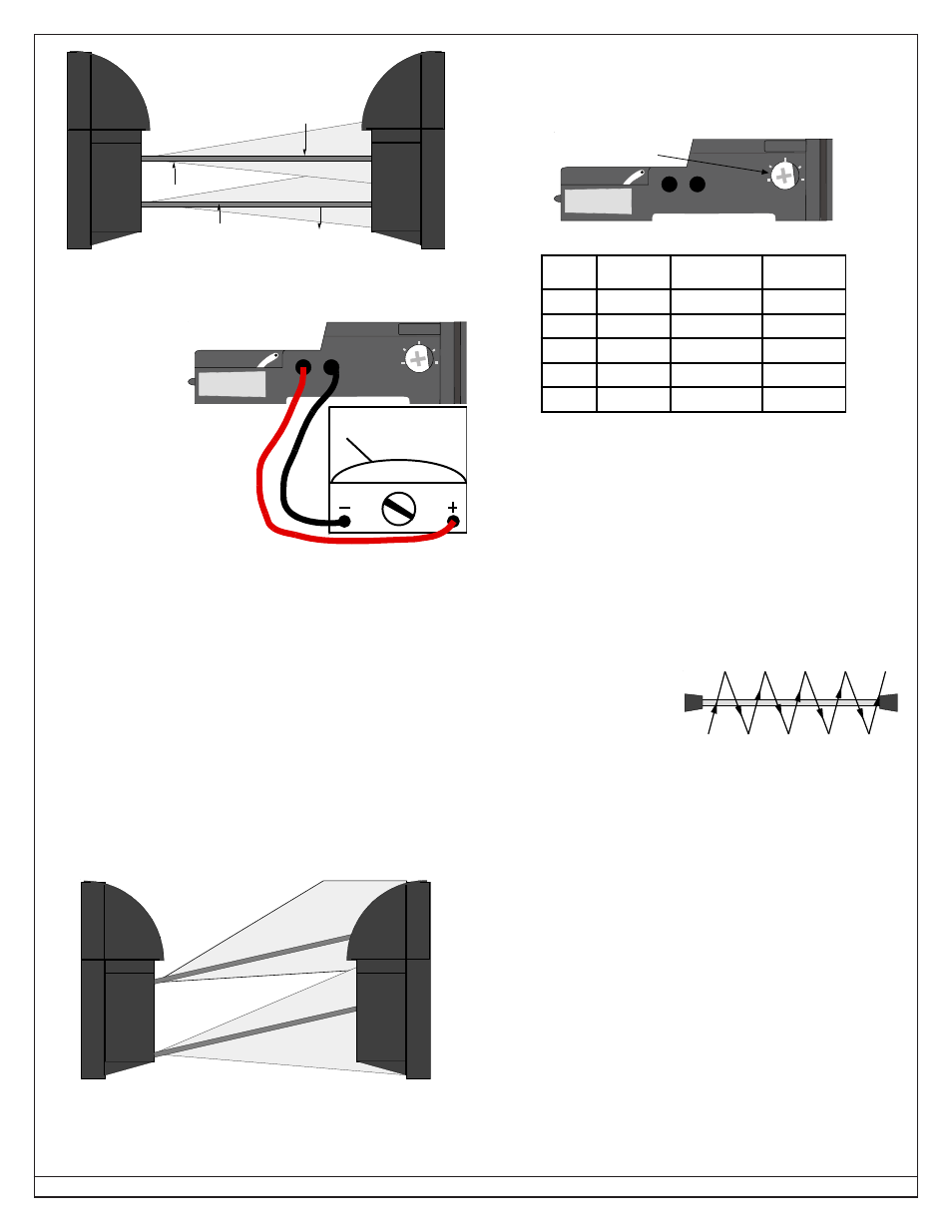
Transmitted Beam
Transmitted Beam strength is
strongest along this path
Transmitted Beam weakens
farther from its center
Receiver's Line-of-Sight
Figure H - Beam Strength Area
• Set the meter to read 3 to 5 VDC.
• Fine peak the transmitter. Connect the meter to the receiver’s test
terminals (see Figure J).
• Rotate the transmitter’s optical module very slightly to the right and
left until a maximum meter reading has been achieved. If you cannot
obtain a reading greater than 2.3 VDC, the Transmitter and Receiver
must be realigned using the procedure in section 5.0.
NOTE: To aid in fine-tuning the system, the red LEVEL LED gets
brighter as the units get fine-tuned and the green GOOD
LED will be on when the meter readings reach a peak.
• Adjust the transmitter’s Vertical Fine Tuning screw slightly until
maximum meter readings have again been achieved.
• With the transmitter’s optical module fine-tuned, repeat this exact
process with the receiver.
7.0 Final Check
• Completely block the upper beam on the transmitter. Neither the
ALARM LED nor the LEVEL LED should come on. If either does
come on, the beams are incorrectly aligned (see Figure K) and
should be re-aligned.
Figure K - Mis-aligned beams
• Completely block the lower beam of the transmitter. Again, neither
the ALARM LED nor the LEVEL LED should come on.
• If necessary, re-align and fine-tune each unit.
7.1
Alarm response time
The system’s sensitivity to alarms is manually adjusted by the
RESPONSE TIME Control on the receiver (see Figure L1 and Table
L2).
LEVEL
+ -
1
2
3
4
5
RESPONSE
TIME
R
E
C
E
IV
ER
Response Time
Control
Figure L1 - Response Time Control
SETTING
RESPONSE
TIME (ms)
RESPONSE
SPEED
CATCH
EXAMPLE
1
50±25%
23 ft./s (7 m/s)
running
2
210±25%
4 ft./s (1.2 m/s)
jogging
3
380±25%
2.3 ft./s (0.7 m/s)
quick walk
4
540±25%
1.6 ft./s (0.5 m/s)
walking
5
700±25%
1 ft./s (0.3 m/s)
slow walk
Table L2 - Response Settings
A setting near 1 will alarm if a person runs through the beam while a
setting near 5 will alarm for objects moving very slowly through the
beam. The setting should be adjusted lower where birds, debris,
etc., may interrupt the beam path. Be careful not to adjust the setting
too low, or it will not trigger an alarm.
NOTE: In order to comply with the requirements in UL 639, Intrusion
Detection Units, an object passing through the beams at a
speed of 8.8 feet per second (2.7 m/s) must trigger an alarm.
• Walk through the beams after the desired setting has been chosen.
Be sure the system alarms at the desired pace.
• Walk through the beams in several locations between the units
(see Figure M).
• The system should alarm
during each crossing of the
beam. If not, re-check
alignment or trigger
response time.
• Replace the covers.
NOTE: If a tamper circuit
has been installed, it should be tested now by lifting up the
appropriate covers.
• Secure the covers by tightening each cover mounting screw.
8.0 Other Information
8.1 Alignment Lights
Alignment may be made easier by using a flashing high intensity
light placed in front of the units. This makes a very distinct target
when looking at the other unit through the viewing port. A
recommended light source is model AL402.
8.2 Maintenance
At least once a year the front covers should be cleaned. Use a clean
cloth and a common window cleaner.
On a daily basis, the end user should walk through the beams before
arming. This will verify operation.
Figure M - Walk testing the
system
Figure J - Meter connection
NOTE: Observe the Polarity
due to DC voltage.
LEVEL
+ -
1
2
3
4
5
RESPONSE
TIME
R
E
C
E
I
V
ER