Network termination, Network grounding – B&B Electronics MAP450D User Manual
Page 12
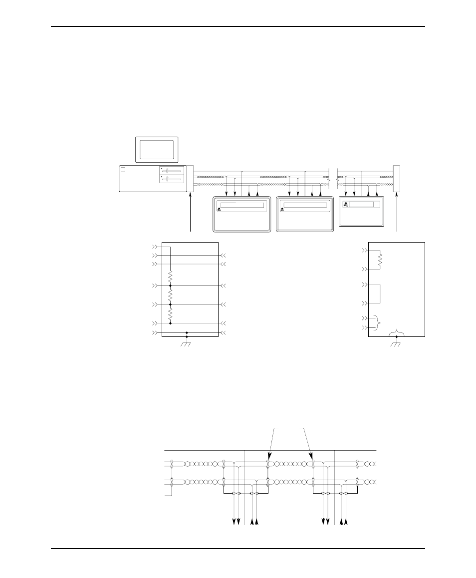
Network Termination
The com-link cable must be properly terminated to reduce the amount of
interference and noise pickup from the surrounding environment. This is
accomplished by using a termination circuit at both ends of the network cable. The
following figure shows a typical termination circuit. The host termination is only
needed if the host controller’s RS-422/485 adapter does not contain any built-in
terminator circuitry. The end termination must be done at the extreme end of the
com-link cable.
Network Grounding
To communicate properly, serious attention must be paid to the grounding scheme
of the devices connected to the com-link. Improper grounding, improper
termination, and faulty shielding of the com-link are the most common causes of
system failure in a multidrop network.
12
MAP450D
1010-0046A, REV 00
Shield
Signal Ground
From Host +
To Host +
Shield
To OIT
To OIT
Signal Ground
From Host
To Host
From Host -
To Host -
HOST TERMINATION
470 Ohm
to
10 KOhm
Tx+
Tx-
Vcc
Rx+
Rx-
SIGNAL GND
CHASSIS GND
EARTH
GROUND
TERMINA
TO
R
HOST
OIT3600
120 Ohm
to
240 Ohm
FROM HOST +
FROM HOST -
TO HOST +
TO HOST -
SIGNAL GND
SHIELD
DO NOT
CONNECT
END TERMINATION
470 Ohm
to
10 KOhm
120 Ohm
to
240 Ohm
MAP460D
OIT3160
TERMINA
TO
R