10 status ok connector p3, 11 dip switch table – ElmoMC SimplIQ Analog Servo Amplifiers-Ocarina Evaluation Board User Guide User Manual
Page 20
2.10
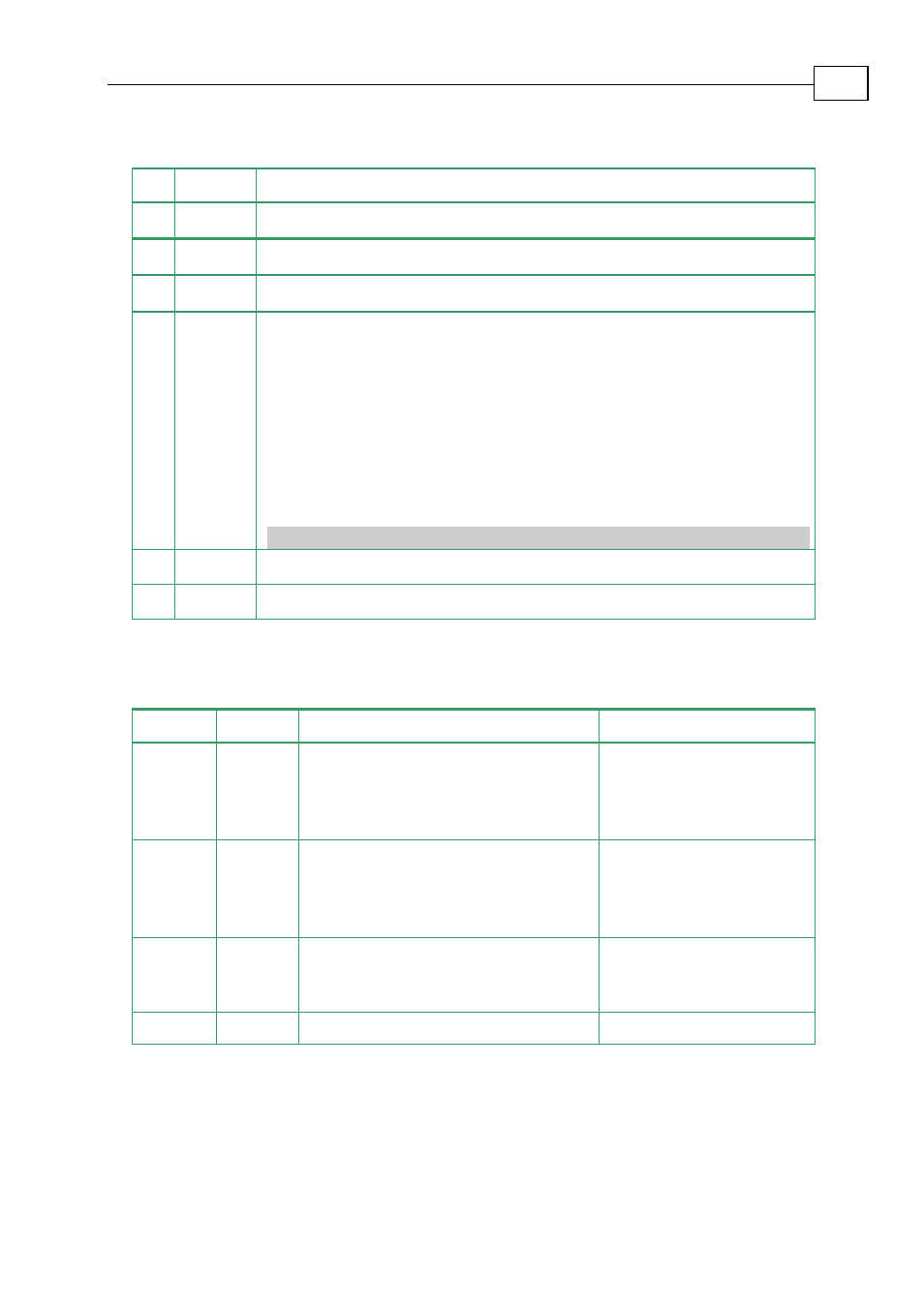
Status OK Connector P3
Pin Function Remarks
1
AOK
Refer to section 3.6.2 in the “Ocarina Installation Guide”
2
SO1
Refer to section 3.6.2 in the “Ocarina Installation Guide”
3
SO2
Refer to section 3.6.2 in the “Ocarina Installation Guide”
4
+VCC
Through this interface, the user can activate and use the “on-board”
LED-Display, by applying a power source between P3/4 and P3/6.
The user can use this supply also for enabling the amplifier (eliminating
the need in connecting another supply between P2/1 and P2/9).
This can be achieved by setting DS1 and DS2 to the “ON” position.
+VCC
min. Voltage = 5 V
+VCC
max. Voltage = 15 V
+VCC
max. Current = 35 ma
6
SORET
Return for +VCC
9
SO3
Refer to section 3.6.2 in the “Ocarina Installation Guide”
2.11
DIP Switch Table
Switches Function ON
OFF
S1
EN+
Applicable for enabling the amplifier
only when the user already applied
+VCC and SORET for LED-Display
Disabling the amplifier
when using +VCC and
SORET also for EN
purposes
S2
EN-
Applicable for enabling the amplifier
only when the user already applied
+VCC and SORET for LED-Display
Disabling the amplifier
when using +VCC and
SORET also for EN
purposes
S3
GAIN
Changing S3 to the "ON" position
reduces the proportional gain (P) of
the current loop by 70%
GAIN-OFF
S4
LATCH Latch mode
Non-latch mode
Table 2-4: Dip Switch Table
Ocarina Evaluation Board User Guide
Evaluation Board Connectors and Cables
MAN-EVLBRD-OCA (Ver. 2.2)
2-12