Fiber-lite, Fig. 2 fig. 3, Fig. 5 table a – Dolan-Jenner PL900 User Manual
Page 4
DOLAN-JENNER INDUSTRIES, 159 Swanson Road, Boxborough, MA 01719, U.S.A., 978-263-1400, FAX: 978-264-0292
4
Lamp Fail Signal:
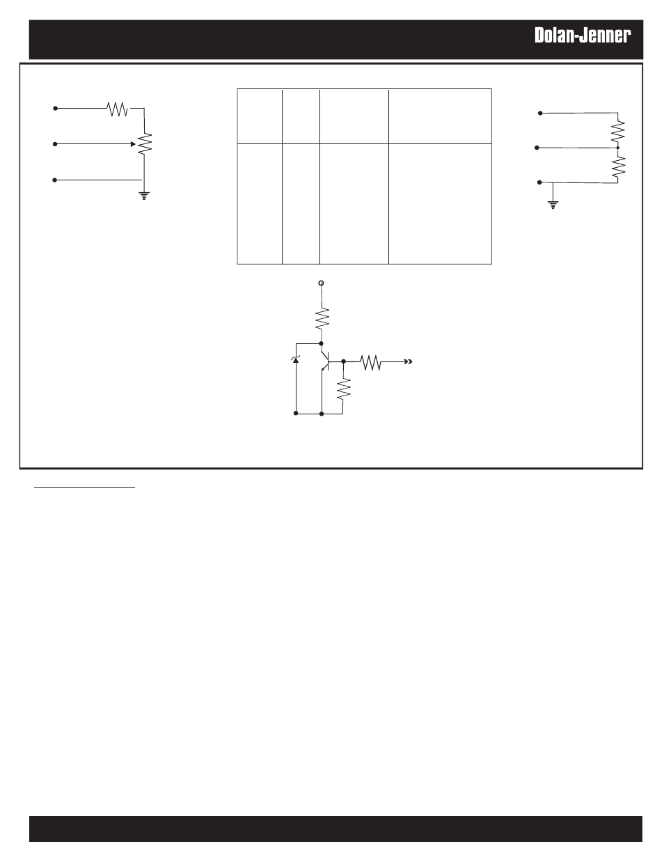
A signal indicating that the lamp has failed is available on Pin 9. This signal is open collector (see Fig 5). The
user must supply the necessary circuitry to connect the lamp out signal to a signaling device. The maximum
current through the circuit is 10 mA. When the signal at Pin 9 is logic High(5v) the lamp has failed.
The Lamp Fail signal will detect if current has stopped flowing to the lamp while the intensity control signal is
not at 0 volts, the illuminator On-Off switch is in the On position and the Remote On-Off signal is in the On
condition. The Lamp Fail signal will also indicate if the lamp is not properly seated after a lamp change or if the
lamp power connector is not properly connected after a lamp change or if the lamp socket was replaced.
Pin 1
+5
Pin 3
Pin 2
R
A
R
B
Pin 1
Pin 3
Pin 2
R = 500W
A
potentiometer
Voltage VDC % @ Full Intensity
(Pin 3)
RA (W)
RB (W)
20K
5.0
100%
20K
2.2K
4.5
90%
20K
5K
4.0
80%
20K
8.6K
3.5
70%
20K
13K
3.0
60%
20K
20K
2.5
50%
13K
20K
2.0
40%
8.6K
20K
1.5
30%
Fig. 2
Fig. 3
R = 50kW
B
47 W
PIN 9
10K
Lamp Fail Ckt.
Fig. 5
Table A
®
Fiber-Lite