145 cm – Comelit FT CB 10 User Manual
Page 6
GROUP S.P.A.
FT CB 10
6
CV
2
CV
7
CV
1
CV
6
CV
5
CV
3
CV
4
145
cm
CV
2
CV
7
CV
1
CV
6
CV
5
CV
3
CV
4
1
2
3
4
5
6
10,2cm
11cm
14,4cm
8,1cm 1,4cm
1,4cm
GENIUS:
10,3cm
10,1cm
BRAVO:
CV
2
CV
7
CV
1
CV
6
CV
5
CV
3
CV
4
1
2
3
4
5
6
CV
2
CV
7
CV
1
CV
6
CV
5
CV
3
CV
4
1
2
3
4
5
6
1
2
Fig. 1
Fig. 2
Fig. 3
Fig. 4
1
2
3
4
5
6
3
2
1
Fig. 5
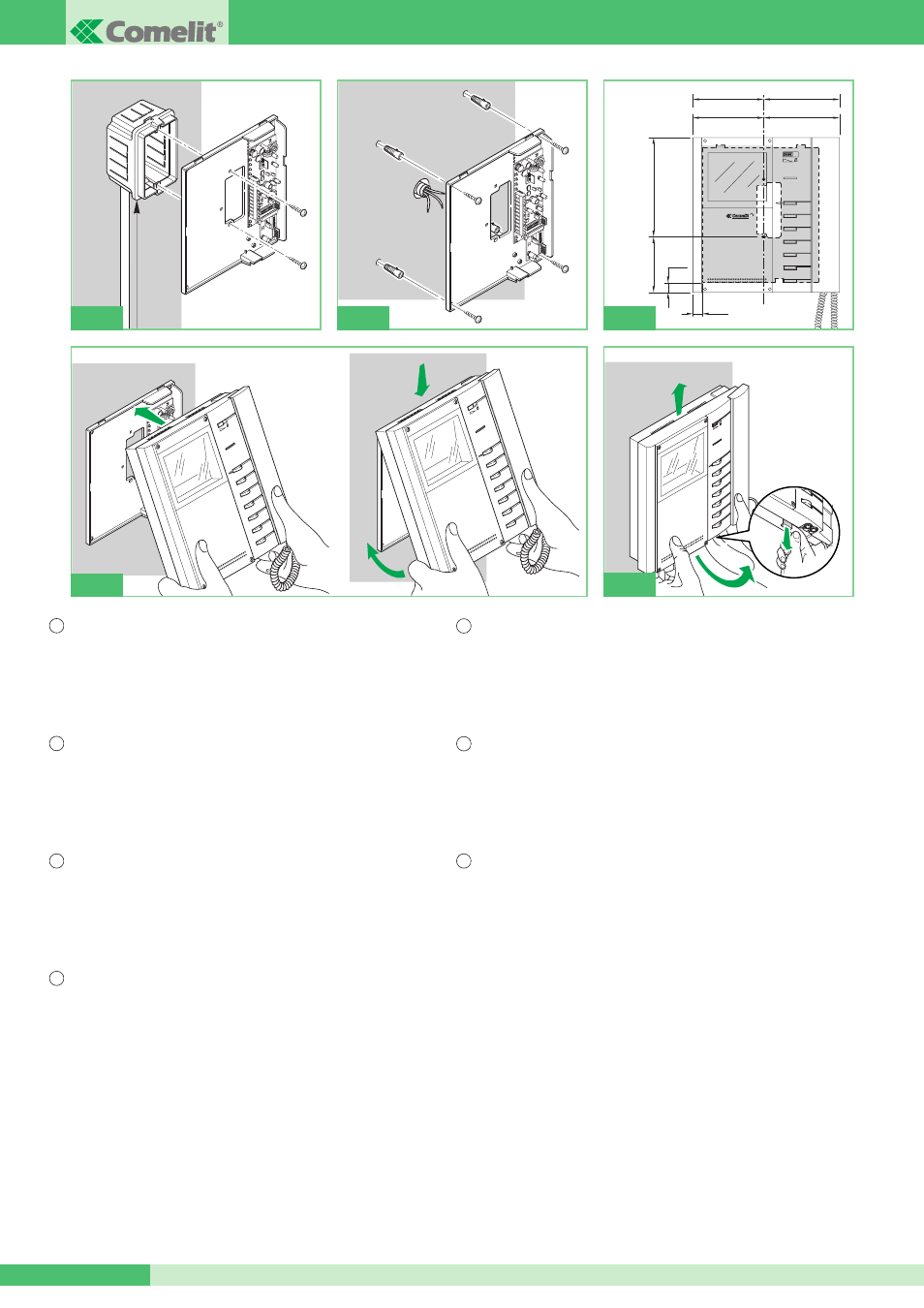
Fig. 1 Installazione Staffa Art. 5808 su scatola serie civile 503 (Art. 4517).
Fig. 2 Installazione a muro Staffa Art. 5808 con 4 viti a tassello (Utilizzabile
eventualmente anche con scatola serie civile 503 Art. 4517 per
migliorare il fissaggio della staffa).
Fig. 3 Misure di ingombro del Monitor in relazione ai punti di fissaggio della
Staffa Art. 5808.
Fig. 4 Procedura di aggancio Monitor.
Fig. 5 Procedura per togliere il Monitor dalla staffa a cui è agganciato.
Fig. 1 Installation of Bracket Art. 5708 on civil series box 503 (Art. 4517).
Fig. 2 Installation of Bracket Art. 5808 with 4 expansion screws (can also be used,
if necessary, with civil series box 503 Art 4517 to improve bracket fixing).
Fig. 3 Overall dimensions of the monitor in relation to the fixing points of the
bracket Art. 5808.
Fig. 4 Procedure for mounting the monitor.
Fig. 5 Procedure for removing the monitor from the bracket to which it is
hooked up.
Fig. 1 Installation étrier Art. 5808 sur boîtier série civile 503 (Art. 4517).
Fig. 2 Installation murale étrier Art. 5808 avec 4 chevilles (utilisables
éventuellement avec boîtier série civile 503 Art. 4517 pour améliorer la
fixation de l’étrier).
Fig. 3 Mesures d’encombrement du moniteur en relation aux points de fixation
de l’étrier Art. 5808.
Fig. 4 Procédure d’accrochage moniteur.
Fig. 5 Procédure pour enlever le moniteur de l’étrier auquel il est accroché.
Afb. 1 Installatie aansluitgrondplaat art. 5808 op de inbouwdoos voor woningen
503 (art. 4517).
Afb. 2 Wandinstallatie aansluitgrondplaat art. 5808 met 4 schroeven met
pluggen (eventueel ook bruikbaar met inbouwdoos voor woningen 503
art. 4517 om de bevestiging van de aansluitgrondplaat te verbeteren).
Afb. 3 Buitenafmetingen van de monitor in verband met de bevestigingspunten
van de aansluitgrondplaat art. 5808.
Afb. 4 Bevestigingsprocedure monitor.
Afb. 5 Procedure om de monitor van de aansluitgrondplaat los te maken.
Abb. 1 Installation des Befestigungssockels Art. 5808 an Unterputzdose 503
(Art. 4517).
Abb. 2 Wandbefestigung des Befestigungssockels Art. 5808 mit 4 Schrauben
und Dübeln (ggf. auch mit der Unterputzdose 503, Art. 4517, zur
besseren Befestigung des Sockels verwendbar).
Abb. 3 Abmessungen des Monitors in Bezug auf Befestigungspunkte des
Sockels Art. 5808.
Abb. 4 Einrasten des Monitors am Sockel.
Abb. 5 Lösen des Monitors vom Sockel, an dem er eingerastet ist.
Fig. 1 Instalación del soporte art. 5808 en la caja de la serie civil 503 (art. 4517).
Fig. 2 Instalación del soporte art. 5808 en la pared con cuatro tornillos y tacos
(también se puede utilizar con la caja de la serie civil 503 art. 4517 para
mejorar la fijación del soporte).
Fig. 3 Medidas del monitor en relación con los puntos de fijación del soporte
art. 5808.
Fig. 4 Procedimiento de enganche del monitor.
Fig. 5 Procedimiento de desenganche del monitor de su soporte.
Fig. 1 Instalação Suporte Art. 5808 na caixa série civil 503 (Art. 4517).
Fig. 2 Instalação na parede Suporte Art. 5808 com 4 parafusos com bucha
(Pode-se utilizar eventualmente também a caixa série civil 503 Art. 4517
para melhorar a fixação do suporte).
Fig. 3 Medidas de estorvo do Visor em relação aos pontos de fixação do
Suporte Art. 5808.
Fig. 4 Procedimento de encaixe do Visor.
Fig. 5 Procedimento para retirar o Visor do suporte ao qual está preso.
I
GB
F
NL
D
E
P