chiliGREEN K8NHA-M Grand User Manual
Page 17
17
17
17
17
17
English
English
English
English
English
BIOSTAR Motherboard
1
5
1
2
9
10
1
1
(18) Front 1394 Header: J1394A1 (optional)
Pin Assignment
Pin Assignment
1
A1+
2
A1-
3
Ground
4
Ground
5
B1+
6
B1-
7
+12V
8
+12V
9
KEY
10
NA
(19) Digital Audio Connector: JSPDIF_OUT/ (JSPDIF_IN: optional)
The connector is used to connect SPDIF (Sony & Philips Digital Interconnect
Format) interface for digital audio transmission.
Pin Assignment
1
+5V
2
SPDIF_OUT
3
Ground
(20) Flash Rom Read/Write Enable : J3 (optional)
J3
Assignment
Pin1-2 on
Enable the flash Rom to read and write.
Pin 1-2 off
Disable the flash Rom to read and write.
(21) AUDIO DJ Connector: JDJ1 (optional)
Pin Assignment
Pin
Assignment
1
SMBDATA
2
SMBCLK
3
INT_B
4
KEY
5
ATX_PWROK
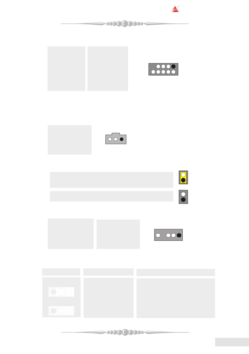
(22) Power Source Selection for IEEE1394: J1394V1 (optional)
J1394V1
Assignment
Description
Pin 1-2 close
+3.3V
3.3V for IEEE1394A connector
located at the J1394A1 header.
Pin 2-3 close
+3.3V Standby Voltage
3.3V Standby Voltage for IEEE1394A
connector located at the J1394A1
header.
1
3
1
3