Operating instructions – Bosch 11320VS User Manual
Page 7
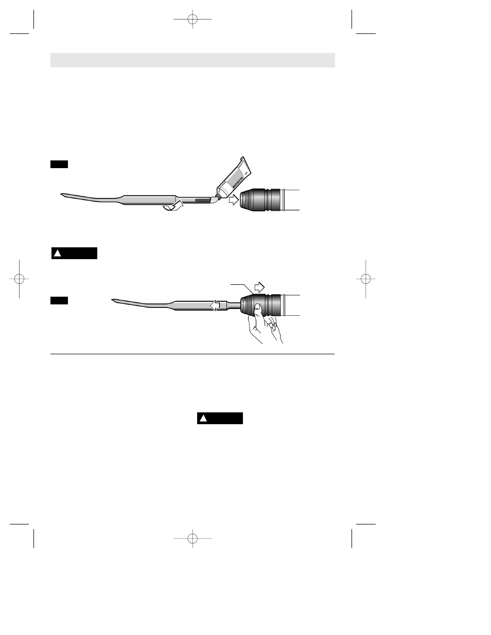
INSTALLING ACCESSORIES
Clean the insert shank end of the accessory
to remove any debris, then lightly grease with
a light oil or lubricant (Fig. 2).
Insert accessory into the tool holder through
the dust shield, while twisting and pushing
inward until it locks automatically into place
(Fig. 2).
Pull outward on the accessory to be certain it
is locked into the tool holder.
NOTE: The high efficiency available from the
hammers can only be obtained if sharp and
undamaged accessories are used. The
"cost" to maintain sharp and undamaged
accessories is more than offset by the "time
saved" in operating the tool with sharp
accessories.
-7-
Operating Instructions
REMOVING ACCESSORIES
Accessories may be hot after
use. Avoid contact with skin
and use proper protective gloves or cloth to
remove.
To remove an accessory, pull and hold
locking sleeve backward and pull bit forward.
All accessories should be wiped clean after
removing (Fig. 3).
!
WARNING
LOCKING SLEEVE
VARIABLE SPEED CONTROLLED
TRIGGER SWITCH
Your tool is equipped with a variable speed
trigger switch. The tool can be turned "ON" or
"OFF" by squeezing or releasing the trigger. The
speed can be adjusted from the minimum to
maximum nameplate BPM by the pressure you
apply to the trigger. Apply more pressure to
increase the speed and release pressure to
decrease speed (Fig. 1).
"LOCK-ON" BUTTON
The "Lock-ON" button, located in the handle
of your tool allows for continuous operation at
maximum RPM without holding the trigger
(Fig. 1).
TO LOCK TRIGGER "ON": squeeze trigger,
depress button and release trigger.
TO UNLOCK THE TRIGGER: squeeze trigger
and release it without depressing the "Lock-
ON" button.
If the “Lock-ON” button is
continuously being depressed,
the trigger can not be released.
AUXILIARY HANDLE
The tool must be supported with the
auxiliary handle, which can be swiveled 360˚.
To reposition and/or swivel the handle,
loosen the hand grip, move the handle to the
desired position along the barrel and
securely retighten the hand grip (Fig. 1).
!
WARNING
FIG. 2
FIG. 3
BM 1619929652 2-04 2/13/04 8:19 AM Page 7