Blue Sea Systems 7727 SafetyHub 250 Fuse Block and Solenoid with Manual Control User Manual
Specifications, Safetyhub 250, Operating instructions
PN 7727 / PN 7727B
PN 7727 includes a Remote Control Contura Switch,
two connector plugs and an Engine Circuit Link Bus
The SafetyHub 250 combines an ignition protected fuse block with a
remote battery switch and integrated connecting plugs. It is safe
for use on gasoline powered boats, reduces connecting wires, and
consolidates up to seven fused circuits. The SafetyHub 250
provides battery control from a remote location and a local switch for
emergency shutdown or servicing.
]
Mount in a dry location.
]
Disconnect all battery connections before beginning the installation.
]
Blue Sea Systems strongly recommends that a competent electrical
professional perform the installation of this product.
]
Do not switch the SafetyHub to OFF while the engine is running.
Damage to the alternator will result.
GUARANTEE: Blue Sea Systems stands behind its products for as long
as you own them. Find detailed information at www.bluesea.com/about.
For customer service, call 800-222-7617.
Amperage Maximum Operating (combined)
(see table below)
Nominal Operating Voltage
12V DC
Minimum Input Cable Size to Meet Ratings
4/0 AWG (120 mm²)
Recommended Ring Terminal
M8 (5/16")
Stud Size
M8 x 1.25
Stud Torque
15 ft-lb (20.3 N-m)
Internal Battery Switch
Continuous Amperage Rating
240A
Cranking Rating: 10 sec.
1,000A
AMI
®
/MIDI
®
Fuse Block
Amperage Maximum Operating (per block)
240A†
Amperage Maximum Operating (per circuit)
170A†
Fuse Amperages Available
30A–200A
Minimum Cable Size to Meet Ratings
2/0 AWG (70 mm²)
Screw Size
M5 x .8 x 10
Screw Torque
27 in-lb (3.0 N-m)
ATO
®
/ATC
®
Fuse Block
Amperage Maximum Operating (per block)
50A†
Amperage Maximum Operating (per circuit)
20A†
Fuse Amperages Available
1A–20A
Regulatory
marked
Meets ISO 8846 ignition protection, and SAE J1171 external ignition protection requirements.
Input Wire Size and Current Derating Table
Remote Control Switch
Contura Control Switch
SPDT ON-ON
Seals
Internal & External Gasket Panel Seal
Operating Temperature Range -40°C to 85°C
Mounting Cut-out
1.450" x 0.830" (36.83 mm x 21.08 mm)
LED Rating
100,000 hours 1/2 life
Regulatory
Meets ISO 8846 ignition protection and UL 1500 external ignition protection requirements
IP67–Protected against immersion up to 1 meter for 30 minutes
The SafetyHub 250 uses a SPDT ON-ON Remote Control Switch for control
from a remote location. The Remote Control Switch should be mounted
in a convenient location for quick access. It incorporates a lockout slide to
reduce the risk of accidental switching.
CAUTION Do not switch the Remote Control Switch to OFF while the
engine is running!
ACTION
OPERATION
LED INDICATION
To switch the battery
bank and high-amperage
circuits
ON
Depress the top part
of the Remote Control
Switch actuator.
LEDs on switch and block
illuminate, indicating that
switched circuits are
ON.
To switch the battery
bank and high-amperage
circuits
OFF
Depress the bottom part
of the Remote Control
Switch actuator.
LEDs on switch and block do
not illuminate, indicating that
switched circuits are
OFF.
Unswitched Fused Circuits
Fused circuits A, B, C, and D are always on 24-hour, (non-switched), regardless
of the Remote Control Switch and manual override switch states
(see Illustration 1.2 - System Diagram on reverse side).
Fuses
Unlatch the two yellow tabs on the fuse cover to access fuses.
The
ATO
®
/ATC
®
Fuse Block of the SafetyHub 250 is used for 24-hour
(non-switched) circuits. The total continuous amperage of this block must not
exceed 50A.
The AMI
®
/MIDI
®
Fuse Block of the SafetyHub 250 is used for the switched circuits.
The total continuous amperage of this block must not exceed 240A.
Engine Link Bus
Use the Engine Link Bus in place of a AMI
®
/MIDI
®
fuse for a switched engine
starting circuit. (See illustration 1.2 on reverse side.)
Indicator LED
The SafetyHub LED will illuminate when the battery switch and high-amp
switched circuits are
ON.
The manual control override knob overrides the Remote Control Switch
and provides:
• An added level of safety that allows manual ON-OFF control with or
without power
• LOCK OFF position for servicing the electrical system or to disconnect the
battery bank and high-amperage circuits in an emergency
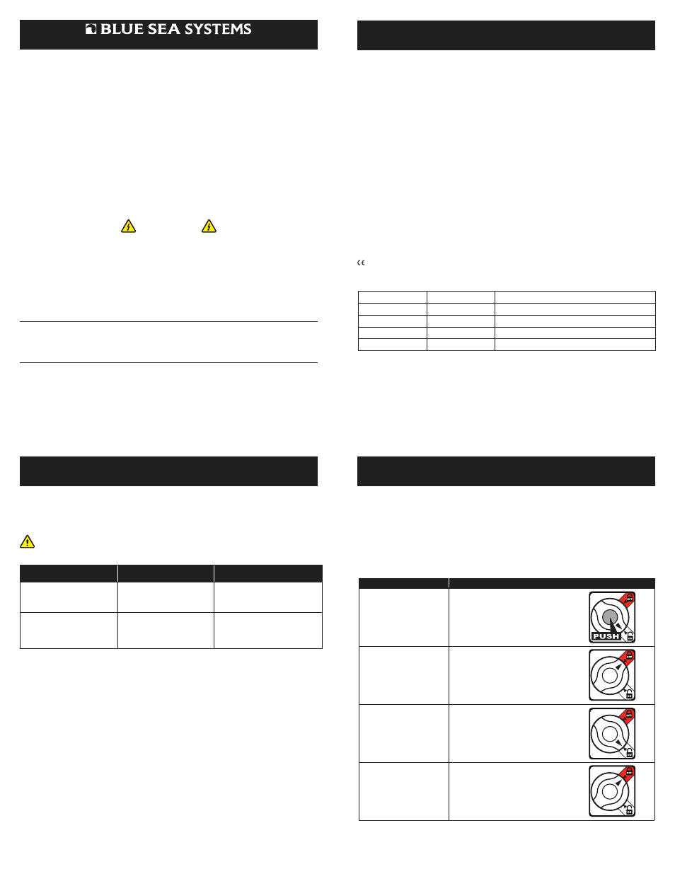
Manual Control Override Operations
Battery bank and high-amp switched circuits 1,2, and 3 only:
ACTION
OPERATION
To switch the
SafetyHub 250 ON
See Note
Turn manual control knob to the
ON position and push button
until latched.
To switch the
SafetyHub 250 OFF
Rotate manual control knob
to the
OFF (red) position
(switch contacts open).
To switch the
SafetyHub 250 back
to READY
Rotate manual control
knob back to the
ON position.
To prevent remote
operation of the
SafetyHub 250
for
SERVICE LOCKOUT
Rotate manual control knob
to the
OFF (red) position.
Marine Electrical Products
SafetyHub 250
Fuse Block with Remote Battery Switch
Blue Sea Systems Inc.
p 360.738.8230
425 Sequoia Drive
f 360.734.4195
Bellingham, WA 98226 USA
www.bluesea.com
980004730 Rev.004
Operating Instructions
(continued)
Specifications
Operating Instructions
WARNING
Note: If either the manual control knob or the Remote Control Switch is in the OFF
position, the SafetyHub 250’s internal battery switch and high-amp switched circuits
will be off.
† Ratings are dependent on input cable sized for appropriate amperages.
AWG Wire Size
Metric Wire Size
Amperage Maximum Operating (combined)
4/0 AWG
120 mm²
280A
2/0 AWG
70 mm²
240A
1 AWG
50 mm²
180A
4 AWG
25 mm²
125A