APG PT-L1-C user manual User Manual
Page 5
Rev. A3,10/08
PT-L1-C
5
Automation Products Group, Inc.
APG...Providing tailored solutions for measurement applications
Tel: 1/888/525-7300 • Fax: 1/435/753-7490 • www.apgsensors.com • [email protected]
C. Re-check zero and re-adjust the zero (“Z”) pot if required.
D. Repeat steps B, and C, until no further adjustment is required.
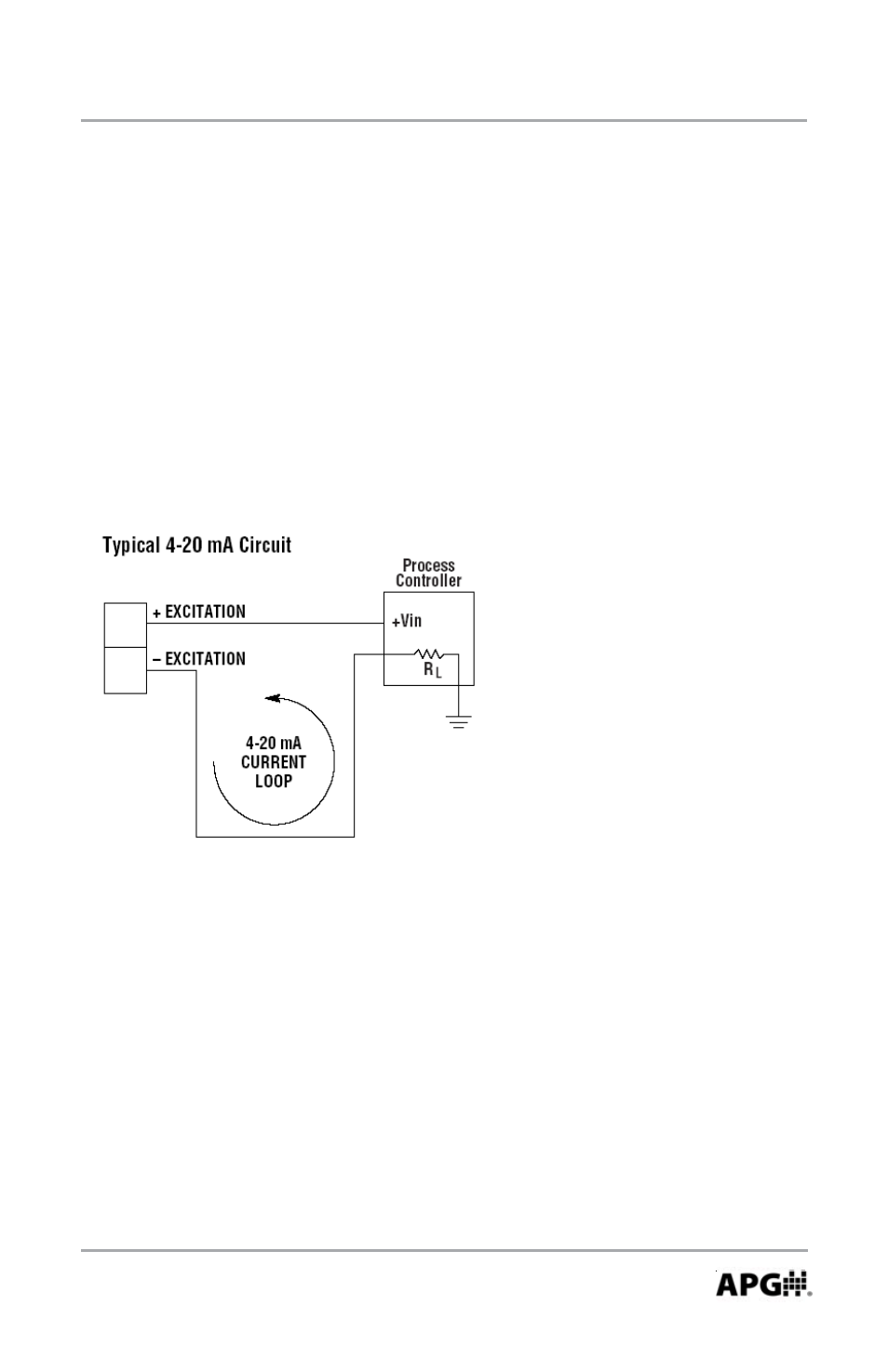
3. 4-20 mA Transmitter Information
This device is a 2 wire, loop powered transducer/transmitter. A voltage of
between 9 and 32 VDC must be maintained at this connection. Completion of the
earth or system ground is recommended for proper circuit protection.
Power supply voltage must be sufficient to maintain a minimum of 9 VDC at
the transducer/transmitter terminals after “dropping” voltage across RL at full
scale current (20 mA), see Figure below.. Example: If RL = 250 ohm then “drop”
is 0.02 Amps X 250 ohm = 5 volts. Therefore power supply minimum is 5 V + 9 V
= 14 V
- LPU-2127 user manual (27 pages)
- LPU-2428 user manual (36 pages)
- MNU Modbus Sensor user manual (40 pages)
- LOE Tank Cloud Master Sensor user manual (36 pages)
- IRU-2000 datasheet (4 pages)
- IRU-3000 datasheet (4 pages)
- IRU-2000 user manual (42 pages)
- IRU-2420 datasheet (4 pages)
- IRU-3430 datasheet (4 pages)
- IRU-5000 datasheet (4 pages)
- IRU-6429 datasheet (4 pages)
- IRU-9400 datasheet (4 pages)
- IRU-3000 user manual (28 pages)
- DST Sensors datasheet (4 pages)
- PT-L1-C datasheet (4 pages)
- PT-L3-C user manual (8 pages)
- PT-L10-C user manual (8 pages)
- PT-L9 datasheet (4 pages)
- PT-L9 user manual (8 pages)
- PT-400 datasheet (4 pages)
- PT-400 user manual (17 pages)
- Hammer Union Pressure Tansmitter datasheet (4 pages)
- Hammer Union Pressure Tansmitter user manual (13 pages)
- PG5 datasheet (4 pages)
- PG5 user manual (28 pages)
- PG7 datasheet (4 pages)
- PG7 user manual (31 pages)
- PG10 datasheet (4 pages)
- PG10 user manual (42 pages)
- PT-500 datasheet (4 pages)
- PT-500 user manual (16 pages)
- PT-500 Modbus user manual (32 pages)
- PT-503 datasheet (3 pages)
- KA Cable Suspended datasheet (6 pages)
- KA Cable Suspended user manual (18 pages)
- FT-100 Cable Suspended datasheet (4 pages)
- FT-100 Cable Suspended user manual (8 pages)
- FL Series datasheet (4 pages)
- FLE Series user manual (12 pages)
- FLR Series user manual (28 pages)
- FLX datasheet (4 pages)
- FLX user manual (16 pages)
- LF Series datasheet (10 pages)
- LFE Series user manual (8 pages)