User options, Remove the base, Configure the internal options – Allen&Heath MixWizard WZ4 14-4-2 User Manual
Page 24: Refit the base, Important
Allen & Heath
24
WZ
4
14:4:2 User Guide
User Options
The MixWizard has a versatile architecture which should satisfy most applica-
tions you may encounter without modification. However, the following inter-
nal options provide alternative settings for those applications that may de-
mand them. Access is required to the internal assemblies. pluggable jumper
links are used in most places and also some links require cutting and soldering
a solder bridge.
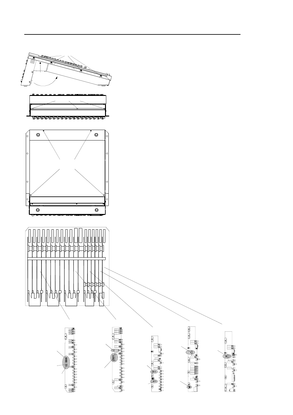
Remove the base
Start by removing the side trims if fitted using a
Pozi crosshead screwdriver. Release the two M4 Pozi head pod securing
screws and rotate the connector pod to gain access to the three M3 rear
base fixing screws. Use a Torx starhead screwdriver to remove these. Ro-
tate the pod again to remove the four M3 underside base screws using the
Torx driver. Carefully lift off the base.
Configure the internal options
Jumper Options:
Fit the options required. Set the option jumpers to the required positions.
Make sure they are pressed fully home. Check that all channels are correctly
set and all options fitted according to their instructions. Make sure that no
debris or parts are left loose inside the console.
Solder Options:
Solder options require some ability with a soldering iron, if you have any res-
ervations then please contact your local service centre to carry out this pro-
cedure for you.
See page opposite for details on how to modify the solder options.
Refit the base
Carefully reposition the base. Refit the fixing screws.
Lock the connector pod in the required position using the securing screws.
Refit the side trims if required.
IMPORTANT:
Check carefully that all channel options are correctly
set as required. Errors on one or more channels now may cause user prob-
lems later. We recommend that you write the repositioned option settings
on a label and adhere this to the rear panel. This would provide a helpful
reference to other users of the console.
REMOVE SIDE TRIMS
REMOVE M4 POZI SCREW PER SIDE
ROTATE POD
REMOVE 4x M3 TORX SCREWS
REMOVE 4x M4 POZI SCREWS PER SIDE
REMOVE 3x M3 TORX SCREWS
ROTATE POD
LIFT OFF BASE
STEREO INPUT
GROUP
MASTER R
AUX PRE/POST FADER
AUX STEREO/MONO
MASTER L
MATRIX AB
BALANCE
AUX 1-4
BALANCE
AUX5
BALANCE
TB MIC
+48V
AUX6
BALANCE
MONO INPUT
AUX PRE/POST FADER
DIRECT OUT PRE/POST FADER
AUX PRE/POST INSERT/EQ
(SOLDER OPTION,
PCB UNDERSIDE)