The gl2 sys-link expander option – Allen&Heath GL2 User Manual
Page 2
2
GL2 SYS-LINK EXPANDER OPTION SHEET AP0204
ALLEN & HEATH
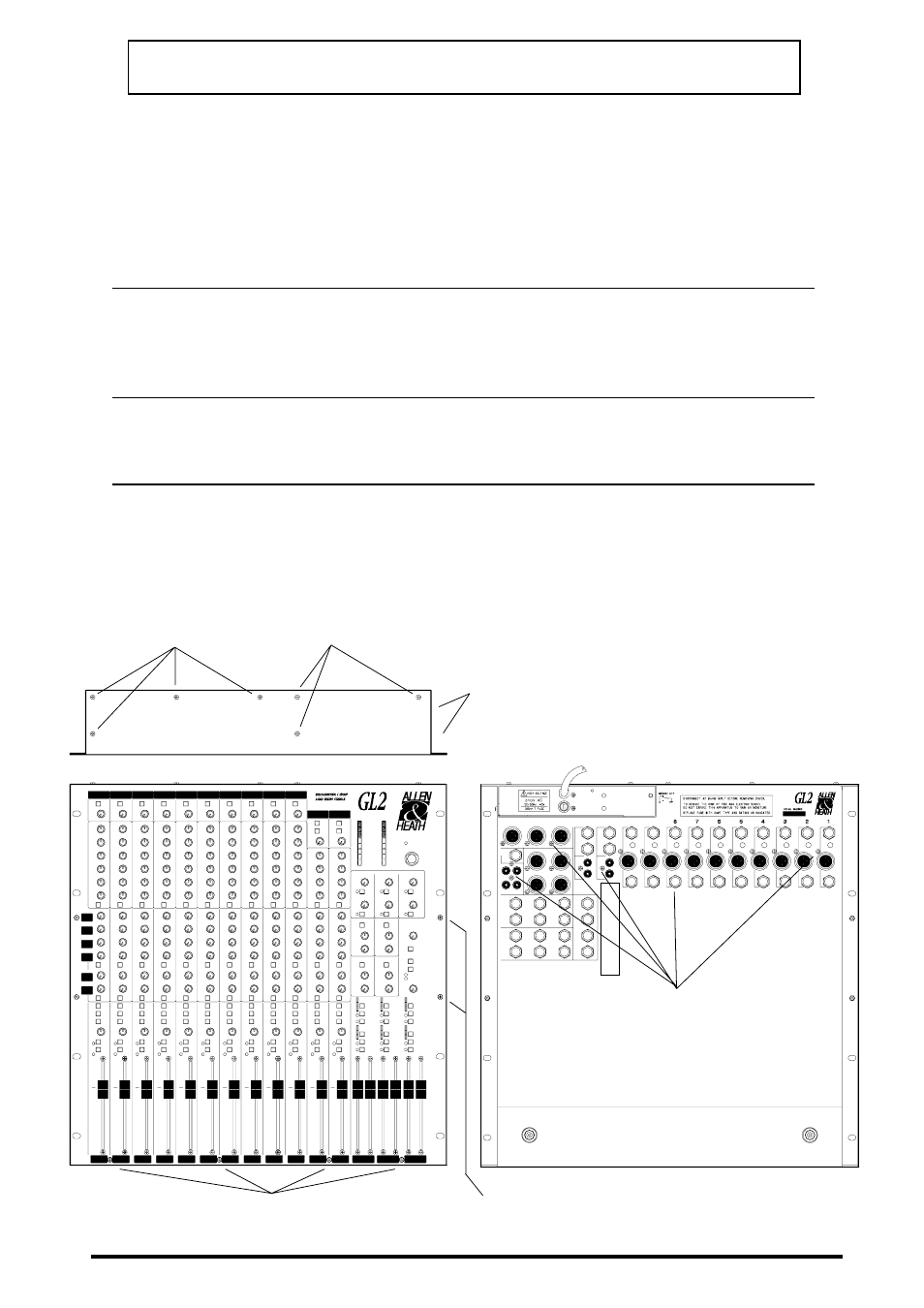
REMOVE 4x FRONT PANEL M3
SCREWS
CAREFULLY LIFT OFF THE
BASE.
REMOVE ALL THE JACK NUTS
(15mm NUTDRIVER) AND 4AB
CONNECTOR SCREWS (XLRs,
PHONOS).
REMOVE 2x POWER UNIT
SIDE M3 SCREWS.
DISCONNECT THE MAINS INPUT, UNPLUG
ALL CABLES AND REMOVE THE CONSOLE
FROM THE RACK OR CASE.
INVERT THE CONSOLE
AND REMOVE 4x M3 BASE
SECURING SCREWS.
REMOVE 4x FRONT PANEL SIDE
M3 SCREWS AND NUTS
n
n
n
n
n
o
o
o
o
o
p
p
p
p
p
q
q
q
q
q
r
r
r
r
r
s
s
s
s
s
t
t
t
t
t
DO NOT REMOVE
THESE 3x POWER
UNIT FIXING SCREWS.
THE GL2 SYS-LINK EXPANDER OPTION
The GL2-SL1(2) option is supplied as a kit of parts to be installed in the ALLEN & HEATH GL2 or
GL2-S console. This allows console to console interconnection via the GL2 SYS-LINK connector
standard.
For information on using SYS-LINK please refer to the separate APPLICATIONS NOTE AP0205.
Access is required to the console internal assemblies. Circuit assembly and soldering is necessary.
THIS WORK SHOULD ONLY BE CARRIED OUT BY TECHNICALLY QUALIFIED PERSONNEL.
1.
CHECK THE CONTENTS OF THE KIT
These are listed on the PACKING SHEET AP0203 enclosed with the kit.
The option comprises a pre-tested circuit assembly with connectors and wiring harness fitted, and a
replacement plug-on IDC ribbon harness.
2.
PREPARE THE WORK AREA
Tools required include a 2-point crosshead screwdriver, 5, 12 and 15mm , longnose pliers, small
wirecutters, and a fine tipped soldering iron.
3. REMOVE THE CONSOLE BASE
Follow the NUMBER SEQUENCE