Appendix, Appendix a: alarm i/o connector – AirLive FE-200VD User Manual
Page 47
5. Appendix
AirLive FE-200VD Manual
41
5
5.
Appendix
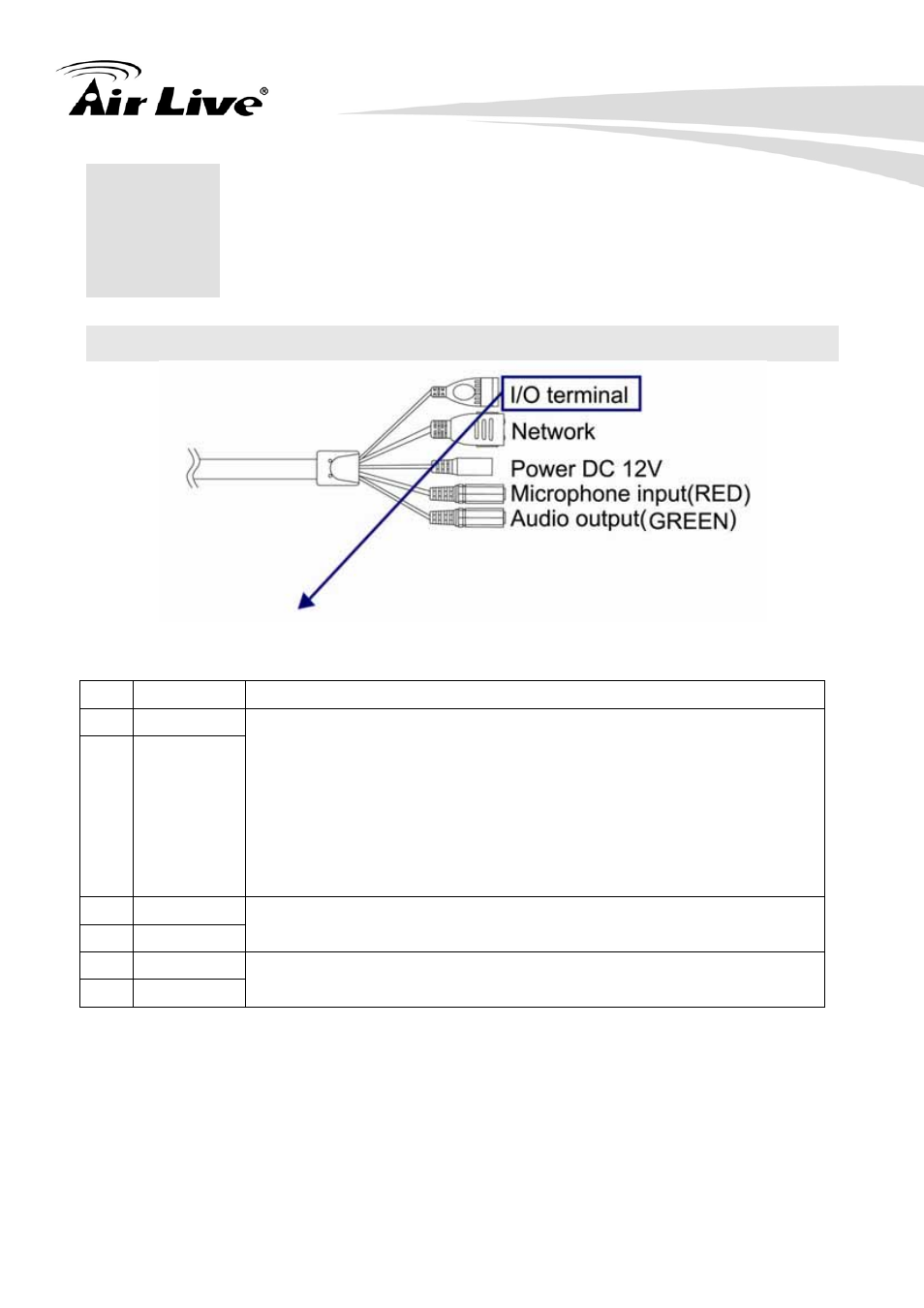
Appendix A: Alarm I/O Connector
This Network Camera provides a general I/O terminal block.
Pin Function Description
1 COM
2 RELAY-NO
Digital output implementation; Pin2 to COM (Pin1) is a
Photo-coupled relay on Normal Open status. External device can
directly connect to the terminals. However the current that will go
through the 2 nodes must not exceed 130mA. An external “Relay”
can also be connected to the terminals as an implementation. In
this case, current (or/and voltage) limitation is specified by the
external Relay.
3 GND
4 DIGITAL-IN
Connect to GND to activate, or leave floating (or unconnected) to
deactivate.
5 GND
6 DEFAULT
PIN with a short wire connecting two revert to factory default
settings.
User can refer to the schematic below to make a proper connection between I/O connector
and external sensor and output device.