3 operating characteristics and limitations, General, Placards – JLG 41EL Operator Manual User Manual
Page 26: Capacities, Stability, 4 controls and indicators, Ground control station (see figure 3-1.), Operating characteristics and limitations -2, Controls and indicators -2, Ground control station -2
SECTION 3 - USER RESPONSIBILITIES & MACHINE CONTROLS
3-2
– JLG Lift –
3120781
3.3
OPERATING CHARACTERISTICS AND
LIMITATIONS
General
A thorough knowledge of the operating characteristics
and limitations of the machine is always the first require-
ment for any user, regardless of user’s experience with
similar types of equipment.
Placards
(See Figures 3-3, 3-4, 3-5 & 3-6.)
Important points to remember during operation are pro-
vided at the control stations by DANGER, WARNING,
CAUTION, IMPORTANT and INSTRUCTION placards. This
information is placed at various locations on the machine
for the express purpose of alerting personnel of potential
hazards constituted by the operating characteristics and
load limitations of the machine. See Foreword at the start
of this manual for a definition of the seriousness of each of
the above placard types. See Decal Location Figures in
this section for decals which apply to this machine.
Capacities
Raising the platform above the stowed position is based
on the following criteria:
• The machine is positioned on a smooth, firm surface
on which the machine is capable of being leveled.
• The load is within manufacturer’s rated capacity.
• All machine systems are functioning properly.
• The machine is leveled and outriggers are properly
installed and locked in place as indicated by the outrig-
ger interlock LED’s on the base frame.
Stability
This machine, as originally manufactured by JLG and
operated within its rated capacity on a smooth, firm and
level supporting surface, provides a stable aerial platform
for all platform positions.
3.4
CONTROLS AND INDICATORS
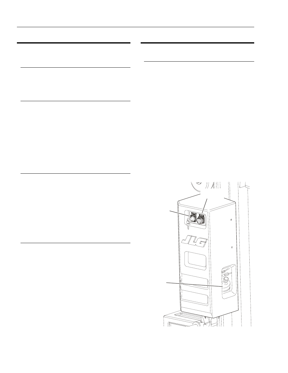
Ground Control Station
(See Figure 3-1.)
NOTE: When the machine is shut down for overnight park-
ing or battery charging, be sure the POWER ON/
OFF KEY SWITCH is positioned to OFF to prevent
draining the batteries.
1.
POWER ON/OFF Key Switch
A key operated power on/off switch located on the
ground control station panel controls power to all
functions on the unit. The machine will not operate
without the key inserted and turned to the ON posi-
tion. When left unattended removing key will prevent
unauthorized machine use.
2.
EMERGENCY STOP Button
An emergency stop (RED button) is mounted on
both the ground control station and the platform
control panel. When the button is depressed, all
machine functions will stop. To re-activate power to
the machine, turn emergency stop button clockwise
until button is reset.
Figure 3-1. Ground Control Station.
EMERGENCY
STOP BUTTON
POWER ON/OFF
KEY SWITCH
HYDRAULIC
OIL
RESERVOIR