2 am-se - straddle extension kit - installation, Description, Straddle adaptor wiring kit components – JLG 41EL Operator Manual User Manual
Page 44: Straddle adaptor wiring installation, Am-se - straddle extension kit – installation -2
SECTION 5 - OPTIONAL EQUIPMENT
5-2
– JLG Lift –
3120781
5.2
AM-SE - STRADDLE EXTENSION KIT –
INSTALLATION
Description
This sub-section contains instructions for installation of
the straddle extension adaptor to AM/EL Series, AC and
DC machines. Also included are instructions for set-up
and operation of the straddle extension kit.
The AM-SE straddle extension kit increases the versatility
of the AM/EL Series by providing a bridge for access to
areas where obstacles such as rows of seats, machines,
counters or stairwells are encountered. The double-winch
elevating system permits one man setup and swivel cast-
ers allow the coupled configuration to be easily maneu-
vered. The unit can be quickly disassembled for compact
storage.
The straddle extension provides clearance of up to 48
inches (1.2m) and the length for caster spacing is adjust-
able from 104 to 128 inches (2.6m to 3.3 m). The AM/EL
Series machines are fully operational at full rated capacity
when used in combination with the straddle extension.
Straddle Adaptor Wiring Kit Components
The straddle wiring kit for both the AM/EL Series includes
the following parts:
1.
Two (2) short wiring harness’ each with a female,
three (3) prong (twist-lock) connector on one end.
These will be wired together and into the existing
harness with three (3) 16 gauge wires - Red, White
and Green - exposed ready for connection.
2.
Two (2) Spring Clips.
3.
Four (4) #10-24 x .625 long bolts, nuts and lock-
washers.
4.
Two (2) 3/8" I.D.\ 1/2" O.D grommets.
Straddle Adaptor Wiring Installation
1.
Set up machine, i.e. install outriggers and level
machine. From outside raise platform as high as
possible to allow access to the wiring on the outrig-
ger interlock relay attached to the back of the center
crossmember on the base frame and also to install
the spring clips which hold the three prong twist-
lock plugs.
NEVER WORK UNDER AN ELEVATED PLATFORM UNTIL PLAT-
FORM HAS BEEN SAFELY RESTRAINED FROM ANY MOVEMENT
BY BLOCKING OR OVERHEAD SLING.
2.
Place a floor jack or other suitable support between
the mast and floor before working underneath plat-
form.
ON AC MACHINES UNPLUG THE POWER CORD, DC POWERED
MACHINES DISCONNECT THE MAIN POWER SUPPLY CONNEC-
TOR ON THE SIDE OF THE BATTERY STORAGE/CHARGER BOX.
THIS WILL PREVENT ANY POSSIBILITY OF GROUNDING ELEC-
TRICAL CIRCUIT AND CAUSING DAMAGE TO UNIT WHILE WORK-
ING AROUND ELECTRICAL COMPONENTS
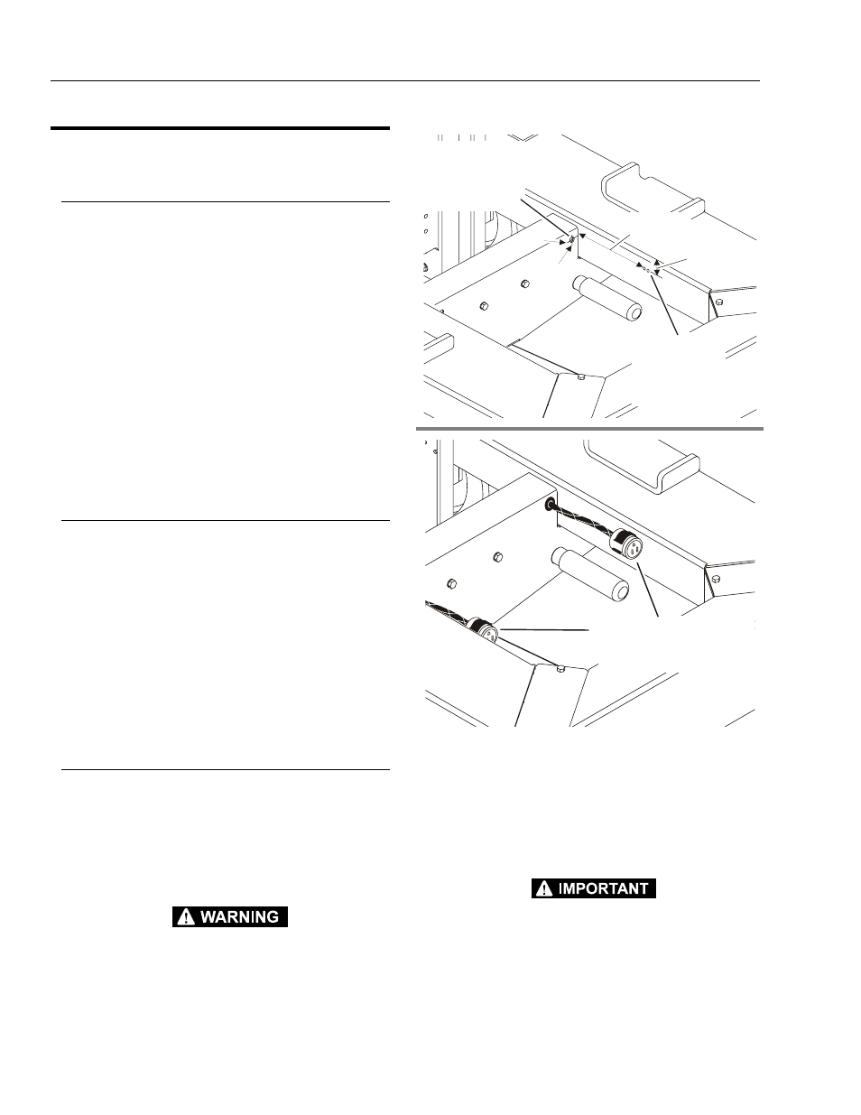
Figure 5-1. SE-Adapter - Wiring Kit
Hole Locations for Grommet & Spring Clips
(Same For Both Sides)
1"
3/4"
6-1/4"
HOLE FOR
WIRING
GROMMET
HOLES FOR
SPRING
CLIP
1-9/16"
ADAPTER WIRING PLUGS
(SHOWN MOUNTED)