Rod assembly installation -8, Holding valve torque specifications -8 – JLG 600SC_660SJC Service Manual User Manual
Page 94
SECTION 5 - HYDRAULICS
5-8
– JLG Lift –
3120898
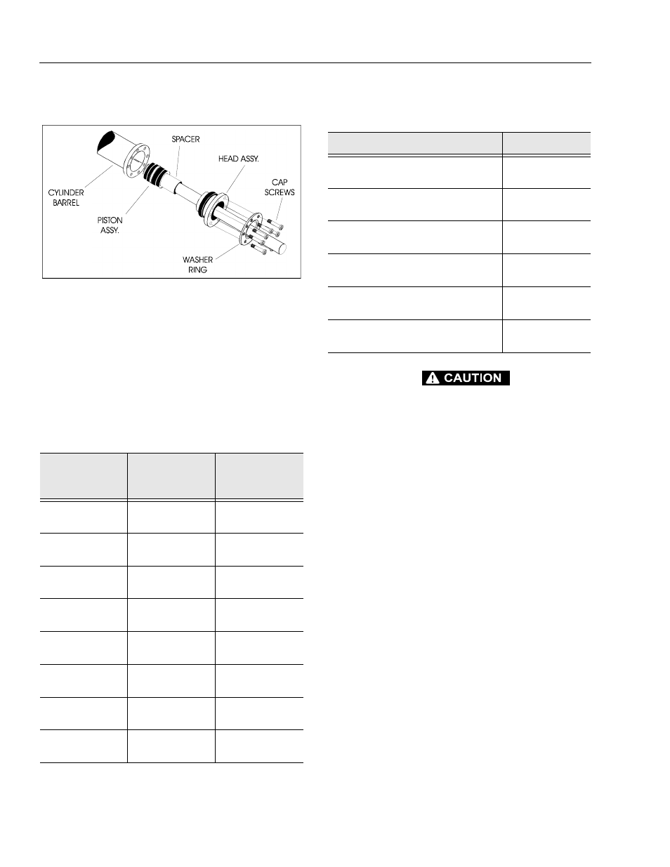
20.
Secure the cylinder head gland using the washer
ring and socket head bolts. (See Table 5-1 .)
21.
After the cylinder has been reassembled, the rod
should be pushed all the way in (fully retracted) prior
to the reinstallation of any holding valve or valves.
22.
If applicable, install the cartridge-type holding valve
and fittings in the rod port block, using new o-rings
as applicable. (See Table 5-2, Holding Valve Torque
Specifications).
IF THE CYLINDER IS TO BE TESTED PRIOR TO INSTALLATION ON
THE MACHINE, EXTREME CARE SHOULD BE USED TO INSURE
THAT THE OUTER END OF THE ROD IS SUPPORTED. USE
EITHER A TRAVELING OVERHEAD HOIST, FORK-LIFT, OR OTHER
MEANS TO SUPPORT THE OVERHANGING WEIGHT OF THE
EXTENDING ROD.
Table 5-1. Cylinder Head and Tapered Bushing Torque
Specifications.
Description
Head Torque
Value (Wet)
Tapered Bushing
Torque Value
(Wet)
Lift Cylinder
275 ft. lbs.
(373 Nm)
30 ft. lbs.
(41 Nm)
Articulating Lift
Cylinder
30 ft. lbs.
(41 Nm)
5 ft. lbs.
(9 Nm)
Slave Cylinder
30 ft. lbs.
(41 Nm)
5 ft. lbs.
(9 Nm)
Master Cylinder
30 ft. lbs.
(41 Nm)
5 ft. lbs.
(9 Nm)
Telescope
Cylinder
50 ft. lbs.
(68 Nm)
9 ft. lbs.
(12 Nm)
Lockout Cylinder
80 ft. lbs.
(109 Nm)
N/A
Articulating Slave
Cylinder
50 ft. lbs.
(68 Nm)
9 ft. lbs.
(12 Nm)
Articulating
Master Cylinder
50 ft. lbs.
(68 Nm)
9 ft. lbs.
(12 Nm)
Figure 5-13. Rod Assembly Installation
Table 5-2. Holding Valve Torque Specifications
Description
Torque Value
SUN - 7/8 HEX M20 X 1.5 THDS.
30-35 ft. lbs.
(41-48 Nm)
SUN - 1 1/8 HEX 1 -14 UNS THDS.
45-50 ft. lbs.
(61-68 Nm)
SUN - 1 1/4 HEX M36 X 2 THDS.
150-160 ft. lbs.
(204-217 Nm)
RACINE - 1 1/8 HEX 1 1/16 - 12 THDS.
50-55 ft. lbs.
(68-75 Nm)
RACINE - 1 3/8 HEX 1 3/16 - 12 THDS.
75-80 ft. lbs.
(102-109 Nm)
RACINE - 1 7/8 HEX 1 5/8 - 12 THDS.
100-110 ft. lbs.
(136-149 Nm)