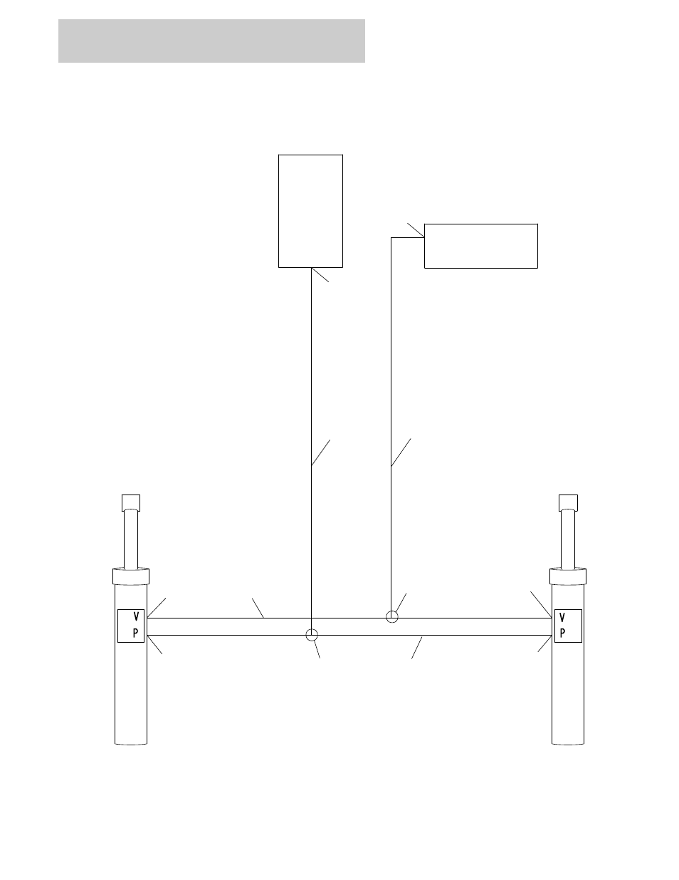
Figure 6-1. axle lockout hydraulic diagram – JLG 860SJ Parts Manual User Manual
Page 190
This manual is related to the following products:
See also other documents in the category JLG Special machinery:
- 120HX Service Manual (116 pages)
- 544D-10 Parts Manual (730 pages)
- 100SX Parts Manual (224 pages)
- 450A Operator Manual (68 pages)
- 15DVL (3121839) Parts Manual (126 pages)
- E450 Operator Manual (116 pages)
- E450 Operator Manual (106 pages)
- G5-18A Operator Manual (142 pages)
- 2505H Operator Manual (148 pages)
- 40HA ANSI Parts Manual (322 pages)
- 400RTS Service Manual (100 pages)
- 600S_SJ Parts Manual (302 pages)
- 660SJ Parts Manual (404 pages)
- 660SJ Parts Manual (306 pages)
- 660SJ Parts Manual (382 pages)
- 660SJ Parts Manual (352 pages)
- 660SJ Parts Manual (310 pages)
- 600S_SJ Parts Manual (299 pages)
- 19AMI (3120758) Service Manual (68 pages)
- 500RTS ANSI Service Manual (80 pages)
- 400RTS ANSI Service Manual (98 pages)
- LSS Scissors (78 pages)
- 510AJ Series II Operator Manual (104 pages)
- 800S Operator Manual (158 pages)
- 800S Operator Manual (130 pages)
- 35xxPS Operator Manual (176 pages)
- 400RTS ANSI Operator Manual (48 pages)
- 500RTS ANSI Operator Manual (46 pages)
- 800A_AJ Operator Manual (134 pages)
- 800A_AJ Operator Manual (150 pages)
- 266 Operator Manual (140 pages)
- G6-42A Parts Manual (478 pages)
- G9-43A Parts Manual (788 pages)
- M400AJP Narrow (108 pages)
- E400 Operator Manual (118 pages)
- 80HX_HX+6 ANSI Operator Manual (104 pages)
- 1350SJP Quick Reference Guide (1 page)
- 1350SJP Quick Reference Guide (2 pages)
- 15VPSP (3120798) Parts Manual (98 pages)
- X14J Operator Manual (169 pages)
- 400S ANSI Service Manual (464 pages)
- X17J Plus Operator Manual (176 pages)
- 20AM Operator Manual (98 pages)
- 3369LE Operator Manual (84 pages)
- 3369LE Operator Manual (86 pages)