15 limit switch adjustment, Speed cutout switch, Drive cutout switch (400 crt) – JLG 400CRT ANSI Service Manual User Manual
Page 32: 16 automatic choke - field adjustment (df-750), Inspection, Adjustments, Limit switch adjustment -18, Automatic choke - field adjustment (df-750) -18, Automatic choke adjustment (df-750) -18, 15 limit switch adjustment speed cutout switch
SECTION 2 - PROCEDURES
2-18
– JLG Lift –
3121111
2.15 LIMIT SWITCH ADJUSTMENT
Speed Cutout Switch
The speed cutout switch is located on the right side of the
frame of the machine. When activated, the switch cuts out
the high drive function. Adjust the switch to activate when
the platform is raised above the stowed position.
Drive Cutout Switch (400 CRT)
The drive cutout switch is located on the left side of the
frame of the machine. When activated, the switch cuts out
the drive function. Adjust the switch to activate when the
platform is raised to 30 ft. (9.1m).
2.16 AUTOMATIC CHOKE - FIELD
ADJUSTMENT (DF-750)
Inspection
NOTE: All automatic choke assemblies have been pre-set to
operate between 20°F and 100°F with little or no
adjustment. If the machine will be operated for pro-
long use outside these temperature ranges, adjust-
ments could be made to improve performance of the
engine.
The machine will take time to warm up and you may
experience low power or rough running for the first
few minutes of operation or until the engine warms
up. LET THE ENGINE WARM UP.
Make sure that the choke shaft operates freely and does
not bind. this can be done without removing the air horn
by rotating the bronze coupling with an eraser on a pencil
or by removing the vacuum pull off line at the manifold
and supply a small amount of vacuum to the hose. the
choke rod should move freely using either method.
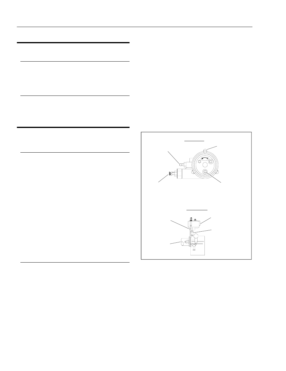
Adjustments
NOTE: If the choke rod is binding make sure the support
bracket is straight
1.
There are two adjustments Vertical (loosening the air
horn nuts) and Horizontal (loosening the bracket to
adaptor screws). These two adjustments should
resolve any binding problem.
2.
To adjust the choke at 70°F ambient, remove the air
horn and reinstall the nut that holds the choke and
support bracket securely making sure the choke
moves freely.
3.
Loosen the 3 top cover screws and rotate the top
cover till the choke butterfly is closed with 1/32 in
space between the plate and the wall of the carbure-
tor.
NOTE: If the machine is run primarily on LP, rotate the top
cover until the choke butterfly is closed with 1/4 in.
space between the plate and wall of the carburetor.
Remember LP fuel needs no choke, all the way open
is ok, if the unit is going to run on LP.
4.
If the ambient temperature is less then 70°F the top
cover counter should be rotated CCW 1 mark for
every 5°F less then 70°F.
5.
If the ambient temperature is more then 70°F the top
cover counter should be rotated CW 1 mark for
every 5°F less then 70°F.
.
RICH
12
VACUUM CONNECTION
VACUUM PULL-OFF
TOP COVER SCREW
POSITIVE CONNECTION
AUTO-CHOKE ASSEMBLY
BRONZE COUPLING
AIR HORN
HORIZONTAL ADJUSTING
SCREWS
SIDE VIEW
TOP VIEW
Figure 2-20. Automatic Choke Adjustment (DF-750)