Steer adjustment for proportional control machines, Pressure settings chart -15 – JLG 3246E2 Service Manual User Manual
Page 27
SECTION 2 - PROCEDURES
3120855
– JLG Sizzor –
2-15
Main Relief Pressure Switch for Non
Proportional Control Machines
1.
Install a pressure gauge at gauge port MP, located at
the bottom front of the valve body. The port is identi-
fied by a stamping on the valve body.
2.
Disconnect the power from the drive valve on top of
the valve body.
3.
Activate drive by moving the joystick to the full for-
ward position.
4.
Adjust Main Relief to value in the pressure setting
chart.
5.
Reinstall the electrical connections to the drive
valve.
Lift Relief Adjustments for Proportional
Control Machines
1.
Install a pressure gauge at gauge port MP, located at
the inside top of the valve body. The port is identified
by a stamping on the valve body.
2.
Disconnect the hose from valve port 3, then plug the
hose and the valve port.
3.
From the platform control station, activate the Lift Up
function by pressing the LIFT switch and activating
the controller to the full forward position.
4.
Adjust Lift Relief to value in the Pressure Settings
Chart.
5.
Shut down hydraulic system and remove pressure
gauge.
Steer Adjustment for Proportional Control
Machines
1.
With pressure gauge at "MP" port on control valve
activate steer in either direction.
2.
Activate drive by pressing the drive switch and acti-
vating the controller to the full forward position.
While holding the controller, activate steer right and
check steer right pressure. If necessary, adjust steer
right pressure to value in the Pressure Settings
Chart.
3.
Activate drive by pressing the drive switch and acti-
vating the controller to the full forward position.
While holding the controller, activate steer left and
check steer left pressure. If necessary, adjust steer
left pressure to value in the Pressure Settings Chart.
Main Relief and High Drive Pressure Switch
for Proportional Control Machines
1.
Install a pressure gauge at gauge port MP, located at
the bottom front of the valve body. The port is identi-
fied by a stamping on the valve body.
2.
Close the steer valve completely by turning clock-
wise.
3.
Once the steer valve is closed activate the steer
switch in either direction until the steer cylinder bot-
toms out.
4.
Adjust your Main Pressure to value in the Pressure
Settings Chart.
5.
Once you have adjusted your main pressure be sure
and reset your steer pressure back to value in the
Pressure Settings Chart.
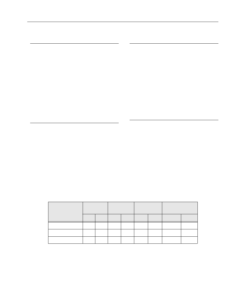
Table 2-3. Pressure Settings Chart
Function
1932E2
2032E2
2632E2/2646E2/
3246E2
3246E2 w/Proportional
Control
psi
bar
psi
bar
psi
bar
psi
bar
Main Relief/High Drive
3200
221
3200
221
3200
221
3000
207
Lift
2300
159
2200
152
2400
165
2100
145
Steer
2000
138
2000
138
2000
138
2100
145