Schematic wiring diagram lpg w/capacitor – Bunn LPG-2E User Manual
Page 21
21
BLK
WHI
RED
RED
10529.0003E 10/98 © 1998
BUNN-O-MATIC CORPORATION
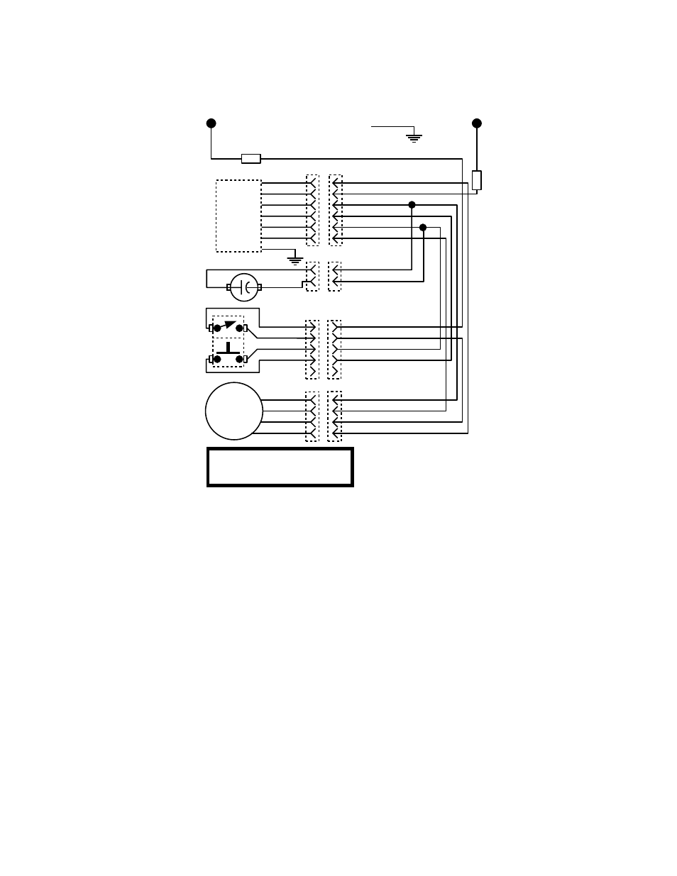
SCHEMATIC WIRING DIAGRAM
LPG W/Capacitor
L1
P1
2
3
4
5
6
1
1
2
RED
WHI/BLK
BLK
WHI/BLU
WHI/BRN
WHI
GRN
RED
WHI/BLK
BLK
BLK
WHI/BLU
WHI/BRN
WHI
BLK
BLK
BLK
RED
WHI/BRN
WHI/BRN
WHI/BRN
WHI/BLU
1
2
3
4
5
P2
BLK
RED
WHI/BRN
WHI/BLU
DC
MOTOR
BLK
WHI
RED
RED
4
1
2
3
P3
GREEN
TIMER
BLK
BLK
N
W
H
I
120 VOLTS AC 2 WIRE
SINGLE PHASE 60 HZ
P4
+
_
27091 111598
This manual is related to the following products: