Eurorack pro rx1602, Control elements and connections – Behringer RX1602 User Manual
Page 5
5
EURORACK PRO RX1602
1.1 Before you get started
1.1.1 Shipment
The RX1602 was carefully packed at the factory to assure
secure transport. Should the condition of the cardboard box
suggest that damage may have taken place, please inspect the
unit immediately and look for physical indications of damage.
+
Damaged units should NEVER be sent directly to us.
Please inform the dealer from whom you acquired
the unit immediately as well as the transportation
company from which you took delivery of the unit.
Otherwise, all claims for replacement/repair may
be rendered invalid.
1.1.2 Initial operation
Please make sure the unit is provided with sufficient ventilation,
and never place the EURORACK on top of an amplifier or in the
vicinity of a heater to avoid the risk of overheating.
+
Before plugging the unit into a power socket, please
make sure you have selected the correct voltage:
The fuse compartment near the power plug socket contains
three triangular markings. Two of these triangles are opposite
one another. The voltage indicated adjacent to these markings is
the voltage to which your unit has been set up, and can be
altered by rotating the fuse compartment by 180°. ATTENTION:
This does not apply to export models that were for
example manufactured only for use with 120 V!
+
If you alter the units voltage, you must change the
fuse accordingly. The correct value of the fuse
needed can be found in the chapter
SPECIFICATIONS.
+
Faulty fuses must be replaced with fuses of
appropriate rating without exception! The correct
value of the fuses needed can be found in the
chapter SPECIFICATIONS.
Power is delivered via the cable enclosed with the unit. All
requiered safety precautions have been adhered to.
+
Please make sure that the unit is grounded at all
times. For your own protection, you should never
tamper with the grounding of the cable or the unit
itself.
1.1.3 Warranty
Please take a few minutes and send us the completely filled
out warranty card within 14 days of the date of purchase. You
may also register online at www.behringer.com. The serial number
needed for the registration is located at the top of the unit. Failure
to register your product may void future warranty claims.
1.2 The users manual
The users manual is designed to give you both an overview of
the control elements, as well as detailed information on how to
use them. In order to help you understand the links between the
controls, we have arranged them in groups according to their
function. If you need to know more about specific issues, please
visit our website at www.behringer.com, where youll find
additional information on mixing consoles, effects units and
dynamic processors.
2. CONTROL ELEMENTS AND
CONNECTIONS
In this chapter we go about describing all control elements of
your EURORACK PRO RX1602. All controls and connectors will
be explained in full detail. You will also receive useful information
about possible applications.
2.1 Channel section
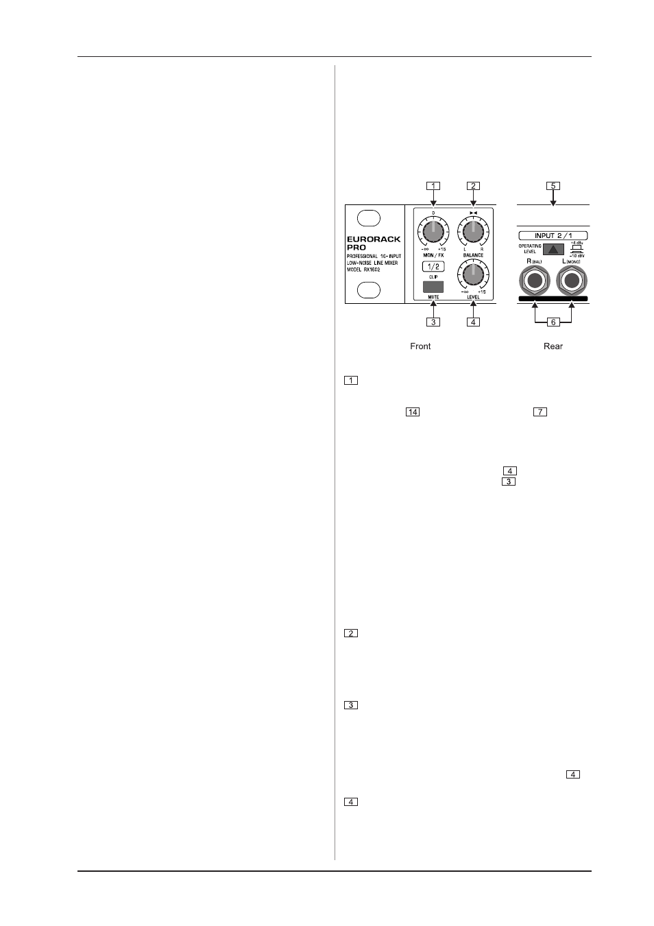
Fig. 2.1: Control elements of the channel section
Use the MON/FX control to set the signal level of the
respective channel for monitoring or effects purposes.
You can take the MON/FX signal at the MON OUT SEND
connector
. The MON/FX SEND control
of the main
section governs the overall MON/FX SEND signal level.
This aux send path is factory set to pre fader and post
mute. It means that the respective channels monitor signal
or effects send signal is still present at the MON OUT SEND-
connector when the LEVEL control
is turned to its left-
most position. If the MUTE switch
is in its depressed
position, the signal is muted totally. The LEVEL control is
equivalent to channel faders on conventional mixing
consoles.
+
You have the option to retroactively make the monitor
channel perform dependently from the setting of the
LEVEL control (post fader). This modification can
be done individually for each channel.
This modification makes sense when you for example wish
to frequently use certain channels for effect applications.
How necessary actions are taken is explained in ch. 5:
AUX CHANNELS MODIFICATION.
By using the BALANCE control, you can
- set up the position of mono signals in the stereo image,
and
- regulate the ratio of left/right channel signals when
processing stereo signals.
The MUTE switch is used to interrupt the signal path, thus
muting the respective channel. When pressed (signal muted)
the switch is lit red.
When the MUTE switch is not depressed, the red light
functions as CLIP display, indicating when the input signal
level is too high (>+17 dBu). To avoid distortion, please
reduce the signal level using the LEVEL control
in
case the CLIP indicator is frequently or permanently lit.
To increase or reduce the input signal level, use the LEVEL
control (increase up to +15 dB, reduce all the way down
to -oo).
Similarly, use the LEVEL controls of the channel sections
to regulate the channels signal level present in the main
mix.
2. CONTROL ELEMENTS AND CONNECTIONS