Rubicon Express RE8000 User Manual
Page 2
bolt into the lower spring pad (ref. step #12). Rotate the coil to
index the spring with lower coil cup.
17. Install the spring retainer clamp removed in step #5.
18. Install longer front shocks. Bar pins may need to be put through the
bottom shock eyes (use light grease).
19. Install adjustable front track bar per instructions supplied with track
bar. Make final adjustment when weight is on vehicle and axle is
centered.
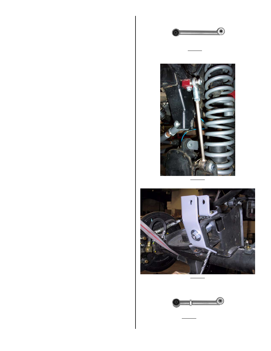
20. Install sway bar quick disconnects per instructions supplied with
disconnects (see photo 2 for typical installation).
-REAR AXLE-
21. Remove the rear shocks.
22. Remove the rear sway bar end links.
23. Support the rear axle.
24. Disconnect rear track bar at axle.
25. Remove all four factory control arms.
26. Remove the rear springs.
27. Remove the plastic dust shield that covers the bolt securing the rear
track bar to the mount on the axle housing and discard.
28. Remove the Torx head bolt (t55) and disconnect axle end of track
bar. If not done previously
29. Install track bar bracket using the supplied ½” bolt and spacer (the
spacer goes in the location vacated by the track bar to prevent the
bracket from deforming when the bolt is tightened - see photo 3 for
similar installation).
30. With the track bar bracket in place, drill two 5/16” holes in the axle
mount where the plastic dust shield was previously located, one on
top and one on angled surface.
31. Install the 5/16” hardware in the holes drilled in step #30. If
required, use supplied horseshoe shim to take up space between
bracket and axle mount at top 5/16” bolt.
32. Install the track bar in the track bar bracket using the Torx bolt
removed in step #28. It may be easier to do this later with weight
on the vehicle.
33. Set lower control arm length to 17.5” for 4.5” lift. Install the lower
control arms with the rubber bushing at the uni-body and super flex
end at the axle. The offset tube should be mounted as low as
possible (zerk on top - see photo 4). Use the factory hardware at
the uni-body and supplied bolt at the axle mount (don’t fully tighten
until vehicle is back on the ground).
34. Set upper control arm length 3/8” longer than stock for a good
starting point (see troubleshooting for drive shaft vibration/pinion
angle adjustment). Install the upper control arms using the factory
hardware (don’t fully tighten until vehicle is back on the ground).
Super flex end should be at axle with zerk on top (see photo 5).
35. Remove the rubber insert from the rear bump stop. Remove the
bump stop cup. Place the spacer between the bump stop cup and
the frame member of the uni-body using the supplied longer metric
hardware (see photo 6). Reinstall rubber bump stop.
36. Install springs. Spring compressors may be helpful.
37. Install replacement sway bar end links.
38. Install longer rear shocks.
39. If installing RE2120 transfer case drop kit (see slip yoke vibration in
troubleshooting) install it now. Support cross member with floor
jack. The cross member is factory mounted with two studs and two
bolts. The studs will have to be removed with a stud remover or by
double nutting them and backing them out. One side at a time,
lower the cross member just enough to insert the spacers at each
bolthole and install bolts and washers.
40. Install all tires.
41. Lower vehicle to ground and adjust front track bar to center front
axle per instructions supplied with track bar.
42. Thoroughly bleed brake lines and check for leaks.
43. Double-check all nuts and bolts to factory torque specs.
44. Test drive and note location of steering wheel. Adjust drag link to
center steering wheel.
45. Align vehicle as soon as practical. A good rule of thumb is minimum
factory caster and maximum factory toe-in.
46.
Recheck all bolts after 50 miles and again after every off road
excursion.
< FRAME END (RUBBER) - PHOTO 1 –AXLE END (ZERK ON TOP) >
PHOTO 2
PHOTO 3
< UNI-BODY END – PHOTO 4 – AXLE END (ZERK ON TOP) >
RI8000 Page 2 of 3