Rubicon Express RE6330 User Manual
Page 2
INSTALLATION OVERVIEW
The installation process can be broken down into the following tasks:
1. Removal of factory lower control arm mounts from uniframe.
2. Front 3- piece crossmember.
3. Control arms.
Step 1 - Removal of factory lower control arm mounts on frame.
First, support vehicle by uni-frame (preferably on a lift) and work on a stable level surface. Support axle with jack
stands and remove factory control arms. Be sure to keep the rear bolts from the upper arms and the front bolts
from the lower arms as they will be reused. It may be helpful to disconnect one end of the track bar to allow some
axle movement for aligning control arm bolts during assembly.
A. Cut off the factory lower control arm mounts from the uni-frame. Use extreme care as not to damage the
uniframe, or cut into existing brake, fuel, or electrical lines.
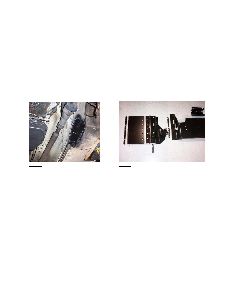
B. Grind rough areas smooth and repaint – refer to Photo 1 for typical bracket removal.
Photo 1
Photo 2
Step 2 - Front 3-piece crossmember
A. First, support transmission/transfer case and remove factory crossmember (and skid plate if there). Loosely bolt
transmission adapter plate to transmission mount so fitment can be checked with new crossmember in position.
The adapter should be positioned with the eight-hole surface up and off set to one side just like the factory
crossmember holes.
B. Note that the factory crossmember is held up by two bolts and two studs. The studs will have to be removed with a
stud remover tool or it may be possible to double nut them and back them out.
C. Refer to Photo 2 for a layout of the right side components of the “3-Piece Crossmember”. Generally align the
center slots of the crossmember over the center slots of the left and right control arm mounts and loosely bolt them
together (through the counter sunk holes in the crossmember into the PEM nut of the control arm mounts) with the
four supplied 1/2” flat head bolts. Loosely bolt assembly up into position with the four supplied 10mm bolts and
flat washers (early models use the front and middle slots and later models use the middle and rear slots) – refer to
Photo 3. Align control arm mounts so their nine holes can be transferred through the horizontal pinch welds along
the inside of the uni-frame rails and tighten the four 10mm and four ½” flat head bolts.
RI6330 Page 2 of 4