Rubicon Express RE7002 User Manual
Page 2
RI7002f Page 2 of 2
bump stop cup and the frame using the supplied longer metric
hardware.
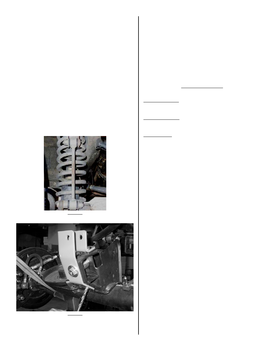
29. Install springs. Spring compressors may be helpful.
30. Install replacement sway bar end links.
31. Install longer rear shocks.
32. If using, install transfer case drop kit by supporting one side of
transfer case with floor jack. Remove hardware from one side of
crossmember. Install spacers and new hardware. Tighten to 55
ft/lbs. Repeat on opposite side. NOTE: If used on a vehicle with
a 6 speed manual transmission contact between the shifter
and body may occur in 2
nd
, 4
th
, and Reverse. In this case it
will be necessary to remove the shift boot to verify for
clearance and possibly modify the body to allow a minimum
of 1/8” clearance between the shifter and the body.
33. Install all tires.
34. Double-check all nuts and bolts to factory torque specs.
35. Test drive and note location of steering wheel. Adjust drag link to
center steering wheel.
36. Align vehicle as soon as practical. A good rule of thumb is minimum
factory caster and maximum factory toe-in.
37.
Recheck all bolts after 50 miles and again after every off road
excursion.
PHOTO 1
PHOTO 2
TROUBLESHOOTING
Rear driveline:
Acceleration vibration: Caused by the pinion being too high in relation to
the transfer case output shaft. Adjust upper control arms or cam bolts
(both optional) to lower pinion accordingly.
Deceleration vibration: Caused by the pinion being too low in relation to
the transfer case output shaft. Adjust upper control arms or cam bolts
(both optional) to raise pinion accordingly.
General vibration: Caused by excessive angle on the rear drive shaft.
Very common on vehicles with 2” or more of lift. It is typically acceptable
to install the included transfer case drop kit and use a standard drive
shaft. Optional cam bolts (RE1475) allow some adjustment of pinion
angle and may be needed (see acceleration and deceleration vibration
troubleshooting above). For best performance, install optional upper
adjustable control arms (RE3783), a slip yoke eliminator (SYE) kit (or CV
yoke on RUBICON model) and CV drive shaft. Adjust pinion so it is 2
degrees below parallel with CV drive shaft (see acceleration and
deceleration vibration troubleshooting above).
A transfer case drop kit
can usually be omitted with a CV drive shaft.
High speed wobble:
This is fairly common with y-type steering on lifted TJ's. It is a condition
where front tires will shimmy after hitting a bump. Avoid bias ply tires
and wheels with excessive offset. Check for worn or loose parts. In most
cases a reduction of positive castor will eliminate this condition. A good
rule of thumb is minimum factory caster and maximum factory toe in.
Note that lift heights increased with coil spacers (or taller coils) may
exhibit wobble that cannot be corrected with alignment.
Bump steer:
Caused by improper relationship of drag link and track bar. To correct,
center axle again following the instructions supplied with the track bar.
Next determine the neutral position of the steering wheel. Adjust the
drag link to center the steering wheel.