Rubicon Express RE7003 User Manual
Page 2
RI7003G Page 2 of 3
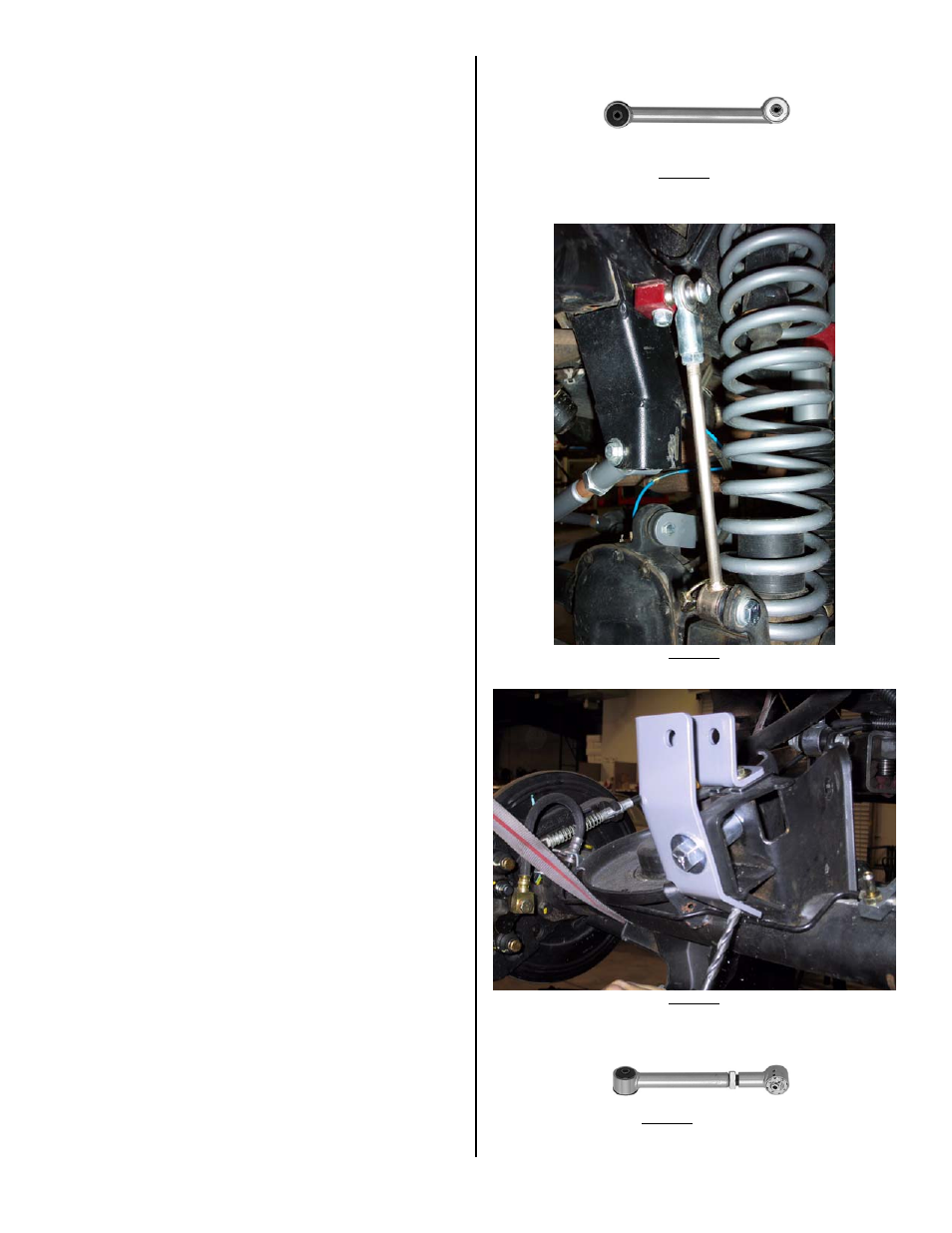
18. Install sway bar quick disconnects per instructions supplied with
disconnects (see Photo 2 for typical installation).
19. Re-drill front track bar axle bracket over toward drivers side ¾”,
center-to- center (or install optional adjustable front track bar).
Reconnect track bar at new hole.
-REAR AXLE-
20. Remove the rear shocks.
21. Remove the rear sway bar end links.
22. Support the rear axle.
23. Disconnect rear track bar at axle.
24. Remove the factory lower control arms.
25. Remove the rear springs.
26. Remove the plastic dust shield that covers the bolt securing the rear
track bar to the mount on the axle housing and discard.
27. Remove the Torx head bolt (t55) and disconnect axle end of track
bar. If not done previously
28. Install track bar bracket using the supplied ½” bolt and spacer (the
spacer goes in the location vacated by the track bar to prevent the
bracket from deforming when the bolt is tightened - see Photo 3 for
similar installation).
29. With the track bar bracket in place, drill two 5/16” holes in the axle
mount where the plastic dust shield was previously located, one on
top and one on angled surface.
30. Install the 5/16” hardware in the holes drilled in step #29. If
required, use supplied horseshoe shim to take up space between
bracket and axle mount at top 5/16” bolt.
31. Install the track bar in the track bar bracket using the Torx bolt
removed in step #27. It may be easier to do this later with weight
on the vehicle.
32. Install the lower control arms with the rubber bushing at the uni-
body and super flex end at the axle. The offset tube should be
mounted as low as possible (zerk on top - see Photo 1). Use the
factory hardware at the uni-body and supplied bolt at the axle
mount (don’t fully tighten until vehicle is back on the ground).
33. If installing optional upper control arms, set length 3/4” longer than
stock for a CV drive shaft (1/4” if trying to use std shaft) as a good
starting point (see general vibration in troubleshooting). Install the
upper control arms using the factory hardware (don’t fully tighten
until vehicle is back on the ground). Super flex end should be at
axle with zerk on top (see Photo 4).
34. If installing optional cam bolts, install per instructions included with
cam bolts (see General Vibration in Troubleshooting).
35. Remove the rubber insert from the rear bump stop. Remove the
bump stop cup. Place the 1-1/2" bump stop extension between the
bump stop cup and the frame using the supplied longer metric
hardware.
36. Install springs. Spring compressors may be helpful.
37. Install replacement sway bar end links.
38. Install longer rear shocks.
39. If using, install transfer case drop kit by supporting one side of
transfer case with floor jack. Remove hardware from one side of
crossmember. Install spacers and new hardware. Tighten to 55
ft./lbs. Repeat on opposite side. NOTE: If used on a vehicle
with a 6 speed manual transmission contact between the
shifter and body may occur in 2
nd
, 4
th
, and Reverse. In this
case it will be necessary to remove the shift boot to verify
for clearance and possibly modify the body to allow a
minimum of 1/8” clearance between the shifter and the
body.
40. Install all tires.
41. Thoroughly bleed brake lines and check for leaks.
42. Double-check all nuts and bolts to factory torque specs.
43. Test drive and note location of steering wheel. Adjust drag link to
center steering wheel.
44. Align vehicle as soon as practical. A good rule of thumb is minimum
factory caster and maximum factory toe-in.
45.
Recheck all bolts after 50 miles and again after every off-road
excursion.
< FRAME END (RUBBER) - PHOTO 1 - AXLE END (ZERK ON TOP) >
PHOTO 2
PHOTO 3
< UNI-BODY END) – PHOTO 4 - AXLE END (ZERK ON TOP) >