Rubicon Express RE7143 User Manual
Page 3
RE7123B Page 3 of 6
Front bump stops and coil springs
A.
Place the front bump stop on the center of the lower spring mount on the axle tube. Insert a center punch thru the center hole in
the bump stop and mark the hole to be drilled. Drill the marked hole to 5/16”, use the supplied self-tapping bolt to secure the
bump stop to the lower spring cup.
B. Raise the small diameter end of the coil into the upper spring bucket and over the lower spring cup and bump stop. Then raise
the axle to seat the upper mount and rotate the coil to properly index in the lower mounts.
NOTE:
If the axle cannot be dropped far enough from the frame due to brake line or ABS wire length to install the coil springs
remove the bump stop and insert it into the coil. Then slide the coil over the stock axle mount and re-install the bump stop bolts.
(PHOTO # 2)
Front Track bar
A.
Set the track bar at an initial setting of 32 7/8”. This measurement may vary due to the weight of your vehicles’ front end. We
advise to pick a common point on both sides of the axle and then cross measure to the opposite side frame rail. By cross
measuring, you are assuring the axle is centered under the vehicle.
B.
Using the stock track bar bolt, install the bushing end into the axle mount. Attach the heim joint end of the track bar to the
factory frame mount using the supplied misalignment spacers and the factory bolt. The bend on the track bar will be with the
elbow up to clear the front differential cover.
NOTE:
It may be necessary to use a ratchet strap to pull the axle to the drivers side and install the track bar. Otherwise wait
until the vehicle is on the ground under its own weight to install the track bar at the frame end. Moving the steering wheel back and
forth will assist in connection the track bar if the vehicle is on the ground.
Front brake lines, shocks, and sway bar links/disconnects
A.
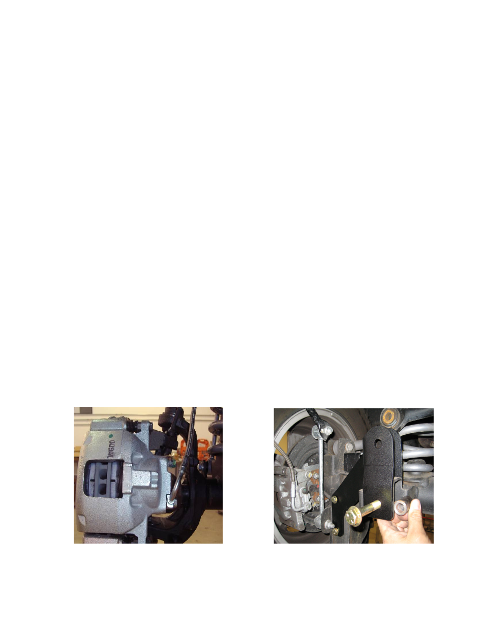
Remove and replace the front brake lines with the included stainless steel brake lines. The lines are left and right specific, when
installed the 90 degree leader from the caliper should be leaning away from the tire. (photo 4, front shown)
B.
Depending on what shocks have been purchased with the suspension system, it may be necessary to reuse the sleeves and bar
pins from the stock shocks. If this is necessary be sure to lubricate the sleeves or bar pins during removal and most importantly
during re-installation.
C.
See supplied instruction sheet for the front sway bar link / disconnect information (RE1143). This kit contains all parts necessary
to be used on a Jeep Rubicon model with factory electronic disconnect as well as X and Sahara Jeep models.
Photo # 4
Photo # 5