Fig. 6, Fig. 7, Fig. 8 – L.B. White 322 Norseman - Horizontal User Manual
Page 9: Fig. 9, Fig. 10
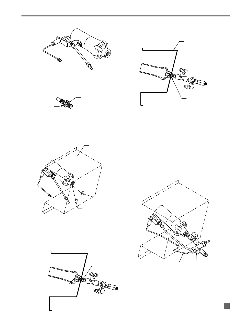
BURNER MOUNTING
BRACKET
JAM NUT TIGHTENED
AGAINST BURNER
MOUNTING BRACKET
THERMOCOUPLE TO SAFETY
CONTROL VALVE
PILOT TUBE TO 90
o
ELL
TIP OF BURNER ORIFICE
IS FLUSH WITH INSIDE
OF BURNER
JAM NUT
BURNER MOUNTING
BRACKET
MOUNTING HOLE
IN BURNER
TAB
6. Thread jam nut onto burner orifice so it butts up
against hex at end of orifice threads. See Fig. 6
FIG. 6
7. Position the burner casting within the burner
mounting bracket. The tab on the burner bracket
must fit within the mounting hole of the burner
casting. See Fig. 7.
FIG. 7
8. Thread the orifice with control assembly into the inlet
of the burner casting so that the tip of the burner
orifice is flush with the inside of the burner and so
the control assembly is positioned as shown. See
Fig. 8.
FIG. 8
9. Tighten the jam nut up against the burner mounting
bracket. See Fig. 9.
FIG. 9
10. Carefully hand form the thermocouple and pilot line
through the hole in the burner mounting bracket to
align with safety control valve. See Fig. 10.
11. Thread the thermocouple connector nut into the pilot
safety control valve. Tighten finger tight and snug
into place with the appropriate wrench. See Fig. 10.
12. Slide the remaining compression nut and sleeve onto
the other end of the pilot line tube. Thread the
compression nut onto the 90 degree elbow at the
safety control valve while firmly pushing the pilot tube
into the elbow. Tighten the compression nut securely.
See Fig. 10.
FIG. 10
9
9
JAM NUT
HEX ON
BURNER ORIFICE