Heater controls, Sediment trap assembly, Warning – L.B. White 220 Plus Therma Grow User Manual
Page 12: Fig. 8
This heater features a two-stage gas control valve and a
heat - ventilation switch. These features expand the
capability of the heater to cost ef fectively maintain
temperature and likewise enhance air circulation in the
greenhouse when heating is not required.
The two-stage gas control valve provides the ability to more
closely match heat to need - starting at the first stage
(minimum or mid-rating position) and only moving to second
stage (maximum or full rating position) if needed to satisfy
the temperature requirements of the building. This
capability results in less temperature variation in the
building and therefore lower fuel consumption. The heater
can be configured to operate in either single stage or two-
stage mode with either a thermostat or building controller.
Note that the heater is wired to start up and run only in the
f i r s t s t a g e p o s i t i o n a s s h i p p e d f ro m t h e fa c to r y.
Connection with a thermostat or building control is
required for further operation. The following instructions
provide interconnections for the two-stage gas control valve
in either single stage or two stage configuration utilizing
e i t h e r a t h e r m o s t a t o r b u i l d i n g c o n t ro l l e r. B e fo r e
connecting any thermostat or building control, become
familiar with the heater’s electrical connection diagram.
See diagrams within this manual or on the heater. Refer to
the index below to select specific wiring interconnections for
the temperature control device to be used.
Index
Page
A.
Two Stage Thermostat
11
B.
Single Stage Thermostat
12
1. Operate on First Stage Heat Only
2. Operate on Second Stage Heat Only
C.
Building Controller Connections - Heating
12
(Using Non-Powered Contacts)
1. Operate on First Stage Heat Only
2. Operate on Second Stage Heat Only
3. Operate Both Stages of Heat
13
The GreenGro incorporates a manual heat - vent switch.
When in the ‘heat’ position, the heater operates normally.
When in the ‘vent’ position, the heater fan operates
c o n t i n u o u s l y. I n t h e ‘ ve n t ’ m o d e , t h e h e a te r t h e n
s u p p l e m e n t s o r p rov i d e s a i r c i rc u l a t i o n w i t h i n t h e
greenhouse. This heat - vent capability can be controlled by
a building controller. Before connecting to a building
controller,become familiar with the heater’s electrical
connection diagram. See diagrams in this manual or on the
heater.
When controlling the heat - vent position with a building
controller, if the building controller is in the ‘vent’ position it
must allow sufficient time for the fan to come to a complete
stop before switching to the ‘heat’ mode.
Regardless of control used:
■
Open the heater’s control box
■
Locate the yellow wire connected from the 24 volt
output of the transformer to terminal W on the
ignition control.
-- Cut this wire at midpoint
-- Strip back insulation on ends 1/2 in.
■
Using proper electrical connectors,connect wiring to
thermostat and gas control valve as shown.
-- Refer to respective diagram
-- Red lead for second stage heat is marked GAS
CONTROL HI.
■
Close and latch the control box when done.
A.
Two Stage Thermostat
Operate on First Stage and Second Stage Heat
HEATER CONTROLS
WARNING
Electrical Shock Hazard
■
Disconnect the heater’s electrical supply before
interconnecting the control.
■
Failure to disconnect the electrical supply will result in
electrical shock.
■
Electrical shock will cause severe injury or death.
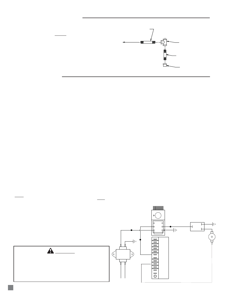
NIPPLE
HOSE ADAPTER
TEE
NIPPLE
CAP
TO GAS CONTROL
VALVE INLET
Assemble the tee, nipples and cap together and tighten
securely. See Fig. 8. The sediment trap assembly must
always be mounted in a vertical position. Make sure pipe
thread compound that is resistant to both L.P. gas and
natural gas is used in making all connections. Check all
connections for gas leaks using approved gas leak
detectors.
FIG. 8
SEDIMENT TRAP ASSEMBLY
11
YELLOW
BLUE
RED
YELLOW
BLACK
WHITE
YELLOW
GREEN
GROUND
BLACK
WHITE
LO
C
HI
GREEN
RED
RED
GAS CONTROL VALVE
HIGH LIMIT
SWITCH
BROWN
GR
OUND
TRANSFORMER
IGNITION CONTROL
2 STAGE
THERMOSTAT
24V
120 V
IND
L1
HSI
HSIG
L2
W
PSI
FSI
GV
PSO
FSG
C
BROWN
BROWN