Testing the manual reset high limit switch, Transformers, Ignition control – L.B. White Guardian with Smart Sense / Direct Connect - Spark Ignition (250K) User Manual
Page 18
TESTING THE MANUAL RESET HIGH LIMIT SWITCH
WARNING
Fire Hazard
■
Do not operate the heater with the high limit switch
bypassed.
■
Operating the heater a bypass high limit switch may
lead to overheating, possibly resulting in a fire, with
subsequent damage to the heater, building damage, or
loss of livestock.
This heater uses a high limit heat switch for the purpose of
over heat protection. The high limit switch is located on the
heat chamber and is connected between the ignition
control and the gas control valve.
The switch has normally closed contacts. If an overheat
condition occurs, the switch contacts will open, thereby
opening the circuit to the gas control valve. The high limit
switch should be tested a minimum of once per year when
the heater is given a thorough cleaning.
1.
Remove the switch. Holding the switch by one of its
mounting legs, apply a small flame only to the
sensing portion on the back of the switch. Do not
melt the plastic housing of the switch when
conducting this test.
2.
Within a minute, you should hear a pop coming from
the switch, which indicates the contacts of the switch
have opened. Check for lack of electrical continuity
across the switch terminals to verify contacts have
opened.
3.
Allow the switch cool down for about a minute before
firmly pressing the reset button on the switch.
4.
Check for electrical continuity across the switch
terminals to make sure the contacts have closed.
5.
Reinstall the switch back into the heater. Reconnect
the heater to its electrical supply. Start the heater
and check for proper operation.
RESET BUTTON
SENSING
SURFACE
TERMINAL
FLAME
MOUNTING
LEG
TRANSFORMERS
The following describes the function of the transformers
located in the control box during a call for heat.
■
The larger 40 VA transformer supplies 24 volts to the
ignition controller to start the ignition process.
-- If 24 volts is not supplied from this transformer
to the ignition controller, the heater will not
operate.
■
The smaller 20 VA transformer supplies 24 volts to
operate the signal conditioner.
-- If this transfomer does not supply 24 volts to the
signal conditioner, the variable rate gas control
valve will operate at low heat only.
FIG. 16
FIG. 15
40 VA
20 VA
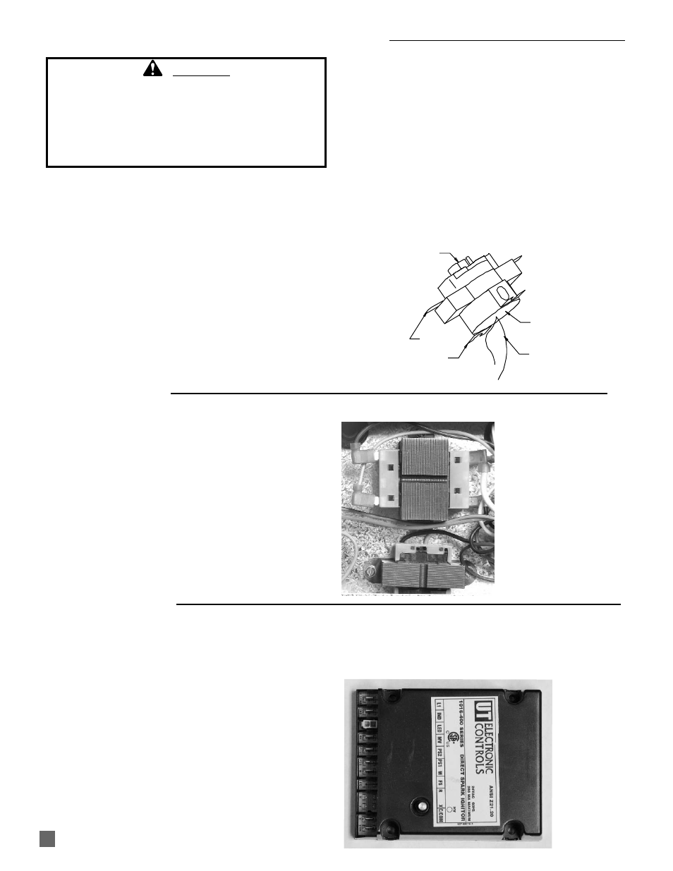
The control sends and receives voltages to operate or verify
operation of components. Refer to the following and Fig. 17 to
understand the ignition control’s terminal designators if doing
voltage checks on the control.
L1: 115 VAC to control from power supply
IND: 115 VAC from control to fan motor
LED: Connection for control’s diagnostic light wiring
harness
MV: 24 VAC from control to high limit switch and then to
gas control valve.
PS2: 24 VAC from air proving switch back to control
PS1: 24 VAC from control to air proving switch
W: 24 VAC from 40 VAC transformer to control (without
this voltage the ignition control will not function)
FS: Microamperage from control to flame sensor for
proving burner flame
R: No terminal
X: No terminal
C/COM: Control and burner ground
Also refer to “Operation Sequence” within this manual as
needed to understand operation of the ignition control during
a call for heat.
FIG.17
IGNITION CONTROL
17