Interconnection for variable heat, Fig. 7, Fig. 8 – L.B. White Guardian with Smart Sense - Spark Ignition (60K / 100K) User Manual
Page 13: Fig. 9, Fig. 10
12
■
The Smart Sense
™
variable rate heater incorporates a
signal conditioner board in the control box. This signal
conditioner takes the control signal supplied from the
building controller and provides the necessary power to
control the variable rate gas control valve.
■
When interconnecting the building controller to the
signal conditioner:
-- Use customer supplied 1/4 insulated female
terminals.
-- Use 18 gauge 2 conductor stranded, shielded
cable for supply of DC volts or milliamp signal from
building controller to signal conditioner.
1.
Open the heater’s control box. for access to the signal
conditioner and wiring connections. See Fig. 7.
FIG. 7
2.
Route the wiring from the building controller through the
liquid tight connector adjacent to the signal conditioner.
See Fig. 7. Securely tighten the connector after wiring
has been connected to the conditioner.
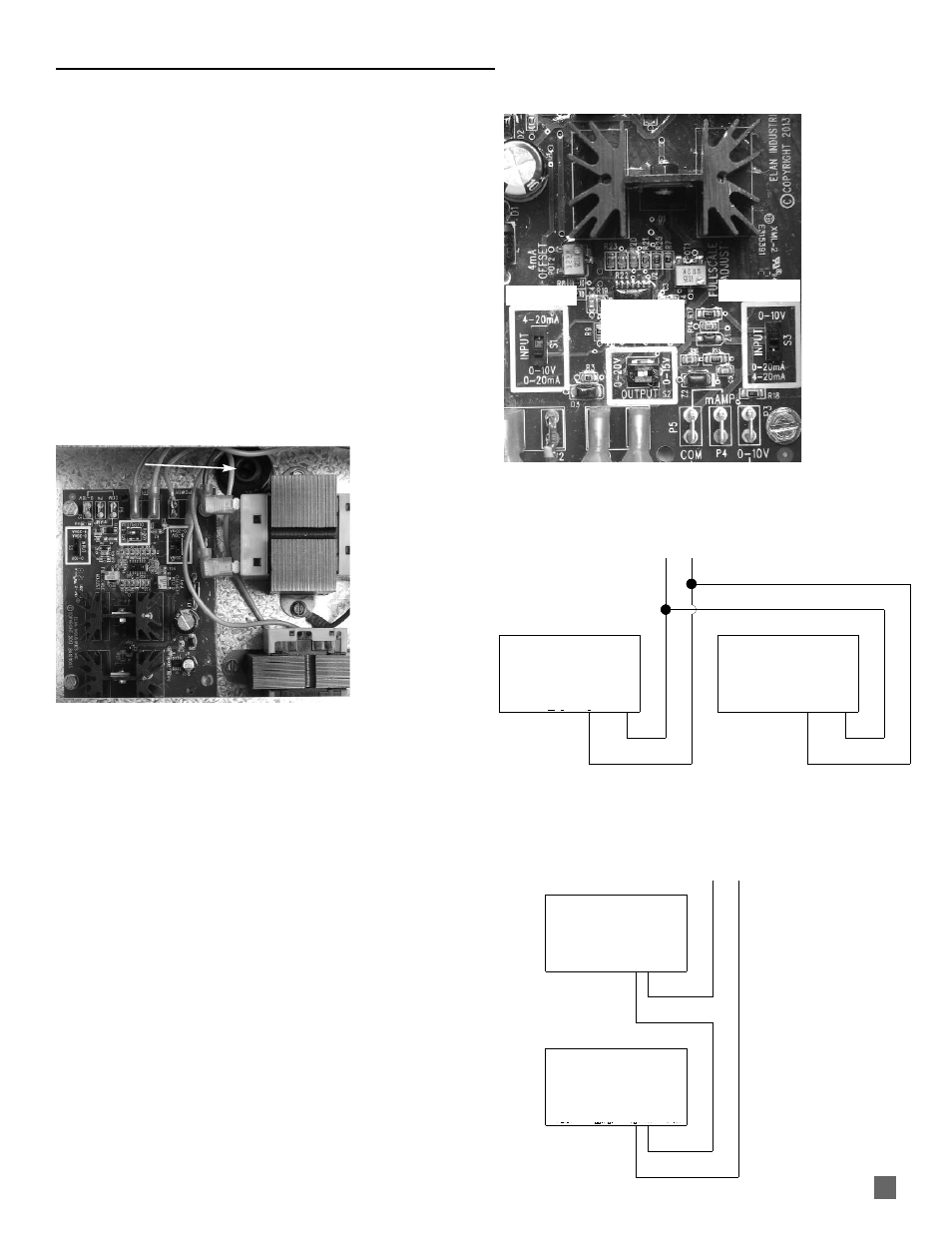
A.
SIGNAL CONDITIONER SWITCH SETTINGS
a. Refer to the following and Fig. 8 for setting the signal
conditioner’s switches to the proper position,
depending on the input signal sent from the
building controller.
b. Ensure the S2 switch is in the 0-15 V position for all
input signals.
■
0-10VDC Input Signal
-- S1 to 0-10 V/0-20mA
-- S3 to 0-10 V
■
0-20 mA Input Signal
-- S1 to 0-10 V/0-20mA
-- S3 to 0-20 mA / 4-20 mA
■
4-20 mA Input Signal
-- S1 to 4-20 mA
-- S3 to 0-20 mA / 4-20 mA
FIG. 8
B.
Connecting building controller with 0-10 VDC output
signal to signal conditioner in heater. See Fig. 9.
FIG. 9
C.
Connecting building controller with 0-20 mA or 4-20 mA
output signal to signal conditioner in heater. See Fig.
10.
INTERCONNECTION FOR VARIABLE HEAT
S2 SWITCH
SET TO 0-15 V
S3 SWITCH
+
SIGNAL CONDITIONER
HEATER 1
SIGNAL CONDITIONER
HEATER 2
P1 P2 P6+ P7- P5 P4 P3
POWER OUTPUT COM mA 0-10 V
P1 P2 P6+ P7- P5 P4 P3
POWER OUTPUT COM mA 0-10 V
-
SIGNAL CONDITIONER
HEATER 1
SIGNAL CONDITIONER
HEATER 2
P1 P2 P6+ P7- P5 P4 P3
POWER OUTPUT COM mA 0-10 V
P1 P2 P6+ P7- P5 P4 P3
POWER OUTPUT COM mA 0-10 V
MILLIAMP COMMON
S1 SWITCH
LIQUID TIGHT
CONNECTOR
SIGNAL CONDITIONER
CHECK WITH BUILDING CONTROL
MANUFACTURER TO DETERMINE ITS
CAPABILITY IN OPERATING MULTIPLE
HEATERS PER CONTROL SIGNAL.
CHECK WITH BUILDING CONTROL
MANUFACTURER TO DETERMINE
ITS CAPABILITY IN OPERATING
MULTIPLE HEATERS PER CONTROL
SIGNAL.
FIG. 10