Fig. 10, Fig. 11, Fig. 12 – L.B. White FA-MCS User Manual
Page 8
d. See Fig.10 for typical connections. Each SmartBox
™
zone can control two heaters.
FIG. 10
D.
Connecting the building controller’s heating contacts to
the SmartBox
™
(for contact closure).
Connect to the red leads as shown in Fig.11. These are
not powered contacts.
-- Remove the wiring from the heat contacts (one for
each zone) in the room controller.
-- Connect these same contacts to the SmartBox
™
Enable wiring Zone 1 and Zone 2, and to common
Zone 1 and Zone 2.
- This allows each SmartBox
™
zone
to operate within the temperature
parameters of the room controller.
FIG. 11
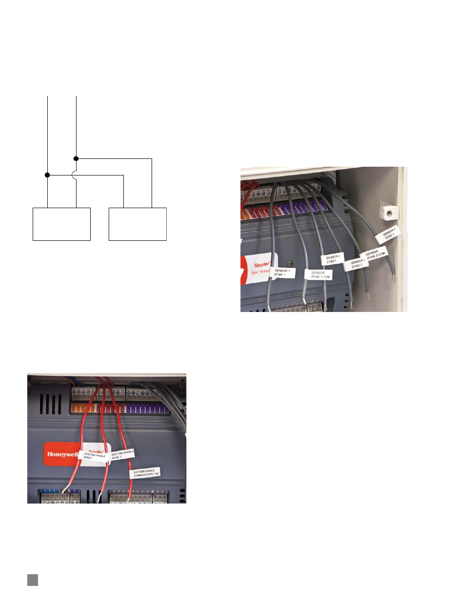
E.
Connecting the SmartBox
™
temperature sensors
Connect 18 gauge 2 wire stranded cable between the
t h e g r ay l e a d s a s s h ow n i n F i g .1 2 a n d t h e
SmartBox™sensor. See page 8 for sensor location.
Solder the connection between the SmartBox
™
sensor
and the 2 wire conductor. Wrap this connection with
electrical tape.
Use only the L.B.White SmartBox
™
sensors, part
number 572815, provided with the SmartBox
™
, or
order replacements as needed. Do not use sensors
from room controllers as these are not compatible with
the L.B.White SmartBox
™
.
FIG. 12
8
ZONE 1 OR ZONE 2 WIRING FROM
Smart Box™
TO
Smart Sense™
VARIABLE RATE GAS CONTROL VALVE
VOL
TS T
O V
AL
VE
VA
LV
E
HEATER 1
GAS VALVE
HEATER 2
GAS VALVE