Igniter and flame sensor – L.B. White AD250(Spark Ignition) User Manual
Page 16
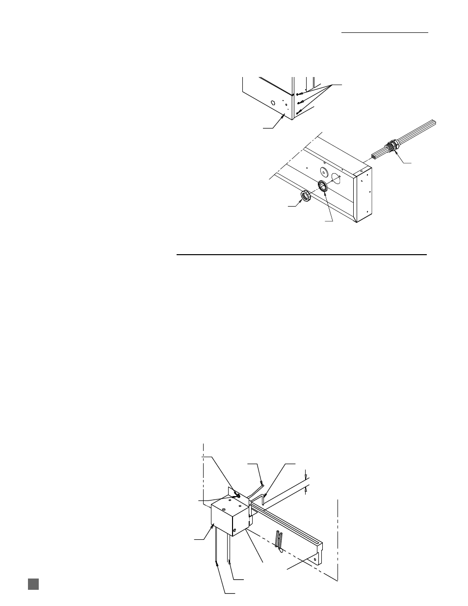
1. Close the fuel supply valves to the heater and
disconnect the heater from its electrical supply.
2. The igniter and sensor assembly is located within a
metal enclosure mounted to the heat chamber above
the burner.
3. The igniter/sensor with its enclosure can be removed
in its entirety. Remove the screw that secures this
assembly to the heat chamber and disconnect the
respective leads from the ignition control. Lift the
assembly from its mounting slots. See Fig. 13.
4. To reassemble, reverse these procedures.
5. Reconnect the heater to its electrical supply. Open
the fuel supply valves to the heater.
6. Start the heater and test for proper operation.
IMPORTANT
■
The igniter/sensor assembly may require cleaning due
to accumulations of dust and dirt over a period of time,
thereby affecting its ability to ignite fuel gas and sense
burner flame. Cleaning will require igniter/sensor
removal.
-- If spark appears to be weak, briskly rub the igniter
electrode with emery cloth or steel wool to remove
any buildup. Recycle the heater.
--- If the spark appears strong but the heater cycles off,
briskly rub the sensor rod with emery cloth or steel
wool to remove any build-up. Recycle the heater.
■
Make sure that the igniter gap is 1/8 In. and the igniter
tip is positioned over the burner port according to the
illustration below. See Fig. 13.
15
SENSOR
IGNITER
4 MM
HEAT CHAMBER FACE
BURNER
IGNITER LEAD
SENSOR LEAD
IGNITER / SENSOR
ENCLOSURE
TO REMOVE IGNITER / SENSOR WITH ENCLOSURE
REMOVE SCREW, LIFT ASSEMBLY
FROM ITS MOUNTING SLOTS
TO GAP IGNITER LOOSEN SCREW.
MOVE ENCLOSURE UP OR DOWN
TO ALLOW PROPER POSITIONING
OF IGNITER TO BURNER.
FIG. 12
1/8 IN.
1. Shut off the gas supply to the heater.
2. Disconnect the heater from its electrical supply.
3. Open the motor access panel.
4. Disconnect flame sensor lead and high voltage
ignition lead from ignition control and route these
back through the rubber grommet in the back of the
control box.
5. Trace and disconnect all remaining electrical leads
which exit the back of the control box from the
components or the areas to which these leads are
connected.
6. Remove liquid tight connector nut and sealing washer
on inside of control box. Pull connector with leads
from back of control box.
7. Remove the three (3) screws on each side of the
control panel and remove the control box from the
heater.
8. To assemble, reverse above procedure.
FIG. 11
TO REMOVE CONTROL BOX AND WIRE HARNESS FROM HEATER
REMOVE 3 SCREWS
(EACH SIDE)
CONTROL
PANEL
NUT, LIQUID TIGHT
WASHER, SEALING
HARNESS
IGNITER AND FLAME SENSOR