Installation instructions, Lift lever kit – Briggs & Stratton 1694561 User Manual
Page 4
4
Installation Instructions
Lift Lever Kit
Form No. 1726469-01
Rev. 11/2006
Briggs & Stratton Yard Power Products Group
Copyright © 2006 Briggs & Stratton Corporation
Milwaukee, WI USA. All Rights Reserved
TP 200-4020-01-AT-SMN
M A N U F A C T U R I N G , I N C .
500 N Spring Street / PO Box 997
Port Washington, WI 53074-0997 USA
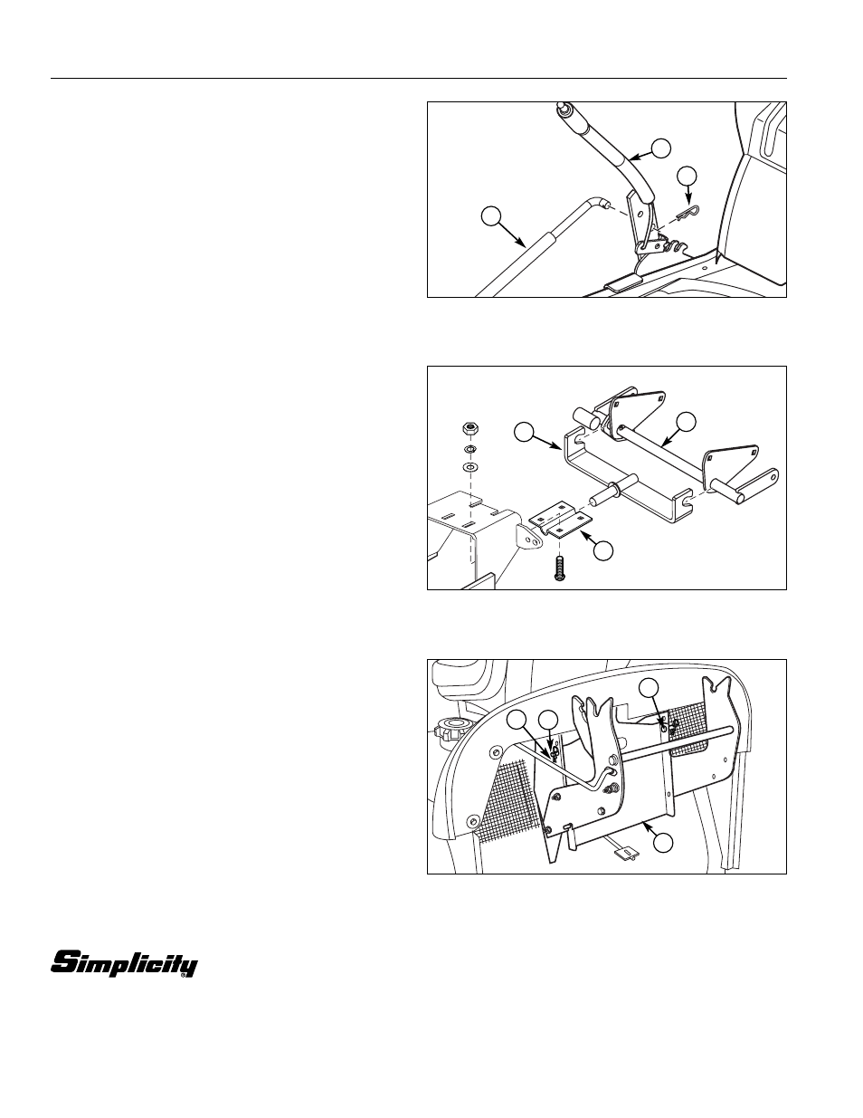
Install Mower Deck
1. Remove Lift Lever Assembly (A, Figure 8).
2. Install mower deck as described in Operator’s
Manual or Dealer Setup Instructions.
B
Figure 9. Install Lift Rod
A. Lift Rod
C. Hair Pin
B. Lift Lever Assembly
A
C
Install Support Assembly
1. Hang support plate (A, Figure 10) onto shaft assem-
bly (B).
2. The post on the support plate (A) fits between the
clamp support (C) and hitch assembly (D). See Sub-
Frame Hitch Installation Instructions for details on
installing sub frame.
B
A
C
Figure 10. Install Support Plate
A. Support Plate
C. Clamp Support
B. Shaft Assembly
D. Hitch Assembly
Figure 11. Install Support Plate
A. Deflector Guard Assy
C. Washer
B. Clevis Pin
D. Hair Pin
Install Deflector Guard
1. Install Deflector Guard Assy (A, Figure 11) using
Clevis Pins (B), Washers (C), and Hair Pins (D) as
shown.
A
B
C
D