JBA 40-9020 User Manual
Installation instructions
INSTALLATION INSTRUCTIONS
** Installation recommendation: JBA recommends in most case that the vehicle be taken to a reputable exhaust shop for installation.
40-9020
2007 Toyota FJ Cruiser 4.0L
Parts List:
Qty. Recommended Tools:
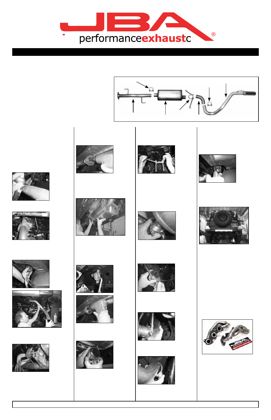
E
D
A. Intermediate pipe
1
14mm socket
B. JBA Muffler
1
Channel lock pliers
C. Turn up pipe
1
Pry bar
D. Tail pipe hanger w/ tip 1
WD40 or equivalent
E. 2-1/2” Clamp
2
F. Muffler hanger clamp 1
A
B
C
E
F
Start:
1. Remove and inventory new JBA
exhaust system.
2. Disconnect negative battery
cable and allow vehicle to cool.
3. With the vehicle raised and
properly supported, spray WD40 or
equivalent on the factory exhaust
clamps and rubber isolators.
4. Unbolt the factory tail pipe above
the rear axle.
6. Next unbolt the intermediate pipe
from the catalytic converter assem-
bly. ***Save the factory hardware
for use later in the installation.
7. Using channel lock pliers remove
the rear muffler hangers from the
(2) rubber isolators and remove the
intermediate pipe / muffler assem-
bly from the vehicle.
10. Install the muffler clamp with
hangers (F) into the rear (2) muffler
hanger rubber isolators with the
hangers shifting pipe to driver side.
11. Insert the center inlet of the JBA
muffler (B) onto the intermediate
pipe (A) with the offset outlet closer
to the center of the vehicle. Make
sure to fully slide the two together
and that the muffler is level and
flat and tighten clamp (E) over the
connection.
15. Install the tail pipe with tip (D)
onto the turn up pipe (C) and insert
hanger into the rear rubber isolator.
Make sure to fully slide the two
together for a tight seal and proper
alignment.
16. Make sure the new system
is properly aligned and their is
adequate clearance on the rear
bumper then tighten the 2-1/2”
exhaust clamp (E).
5. Using channel lock pliers remove
the tailpipe hanger from the rear
rubber isolator and remove the
tailpipe from the rear.
5. Using channel lock pliers pry the
intermediate pipe hangers from the
factory rubber isolators.
8. Insert the JBA intermediate pipe
(A) hangers into the (2) rubber
isolators then bolt the intermediate
pipe to the factory catalytic con-
verter assembly using the factory
hardware.
9. Slide one of the supplied 2-1/2”
exhaust clamps (E) over the end of
the JBA intermediate pipe (A).
12. Slip the rear offset end of the
JBA muffler (B) into the muffler
clamp with hangers (F). The offset
end of the muffler should be toward
the center of the vehicle.
13. Slip the turn up pipe (C) onto
the JBA muffler (B). Position muffler
clamp with hangers (F) over con-
nection and tighten.
14. Slide the supplied 2-1/2”
exhaust clamp (E) on to the turn up
pipe (C).
JBA recommends taking the vehicle to a muffler shop and having all slip connections tack welded.
17. Using a soft cloth, remove all
prints from exhaust tip.
18. Check all clamps and con-
nections for proper fit and align-
ment. Double check all clamps are
tightened and that all hangers are
secure in rubber grommets. It is
recommended that after installation
of the exhaust system you have all
slip connections tack welded by a
muffler shop.
NOTES:
1. All exhaust systems expand
about 1” rearward when exhaust
temperature rises.
Other recommended products:
Get even power for your FJ with
a set of smog legal stainless steel
JBA Cat4ward® headers.
Part No.
Application
2035S
2007 4.0L stainless
2035SJS 2007 4.0L silver ceramic
2035SJT 2007 4.0L titanium ceramic
For more information visit us online
at www.jbaexhaust.com
9.18.06