JBA 40-3047 User Manual
Installation instructions
INSTALLATION INSTRUCTIONS
* Installation Recommendation: JBA recommends in most cases that the vehicle be taken to a reputable exhaust shop.
40-3047
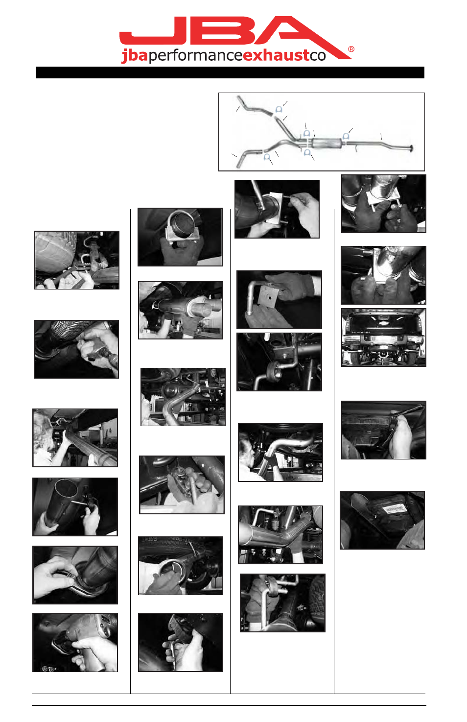
2007 Silverado/Sierra 4.8/5.3L Crew Cab Short Bed
RECOMMENDED TOOLS:
PARTS LIST:
15mm socket
A. Driver’s side tailpipe w/ tip
1
9/16” socket
B. Pass. side tailpipe with tip
1
1/2” socket
C. Driver’s side axle pipe
1
D. Pass side axle pipe
1
B.
E. Muffler
1
F. Intermediate pipe
1
G. 3” exhaust clamps
5
H. Rubber isolators
1
I. Driver’s side frame bracket
1
J. 5/16x1 bolt w/ flat wash, lock washers & nut 1
K. Heat shield (Not Shown)
1
TO START:
A.
C.
D.
E.
F.
G.
G.
G.
G.
G.
1. Remove and inventory JBA exhaust.
2. Disconnect negative battery cable
and allow vehicle exhaust to cool.
9. Slip clamp over intermediate pipe.
15. Install clamp on slip joint. Position
to clear spare tire and leaf spring. Align
tailpipe to clear shock, spare-tire, and
bed crossmember. Snug clamps lightly.
20. Install clamps at rear of muffler
3. Cut factory exhaust behind rear muffler
hanger. Remove hanger rod from
isolator (see photo). Remove tailpipe
from vehicle
4. Remove nuts attaching muffler
assembly, remove hanger rods from
isolators, remove muffler assembly from
10. Install muffler onto intermediate
pipe to insure full insertion. Align so
tailpipes are flat
16. Install left-side rear frame bracket
21. Adjust exhaust system to adeque
on all components and achieve a
symmetrical appearance. Tighten
all fasteners & clamps securely
te
vehicle
5. Install new intermediate pipe.
11. Install right-hand axle pipe. Insert
into right-hand muffler outlet. Mark to
ensure full insertion
into existing hole in frame, behind
tubular crossmember using hardware
provided.
17. Install left-side axle pipe with hanger
rod forward. Slip into muffler, mark to
insure full insertion.
22. Install heat shield for plastic box
at left rear, in front of spare tire.
Remove and re-use front bolt to
attach heat shield
6. Insert hanger rod into isolator
7. Connect using factory nuts
8. Snug nuts lightly to allow adjustment
later.
12. Slip hanger rod into isolator at
front.
13. Install right-hand turnout and tip.
14. Install hanger rod into isolator.
18. Install left-side turnout and tip.
19. Install rubber isolator onto frame
bracket. Install hanger rod into isolator
adjust axle pipe & turnout together to
clear bed crossmember, spare tire, leaf
spring, etc. **Some “adjusting” of brake
line bracket will be necessary. “Adjust”
to allow 2” of clearance between brake
line and exhaust pipe as a minimum
24. After installation, it is recommende
that all clamps be re-tightened.
25. Tack weld all slip connections in
three spots.
26. Lower the vehicle and reattach the
negative battery cable.
NOTES:
1) It may be necessary to loosen and
realign the spare tire for proper
clearance.
2) All exhaust systems will expand abo
1" rearward when exhaust temperatur
start to rise.
3) Use Anti-seize on threads of clamps.
23. Align exhaust tip (D) properly and
tighten clamp (H).
es
d
ut
Rev 4.23.07