Able, Onnections – Philips 14RF50S-71 User Manual
Page 6
6
C
ABLE
B
OX
C
ONNECTIONS
2
I
f you cable signal uses a cable box or
decoder, follow the easy steps below to
complete the connection.
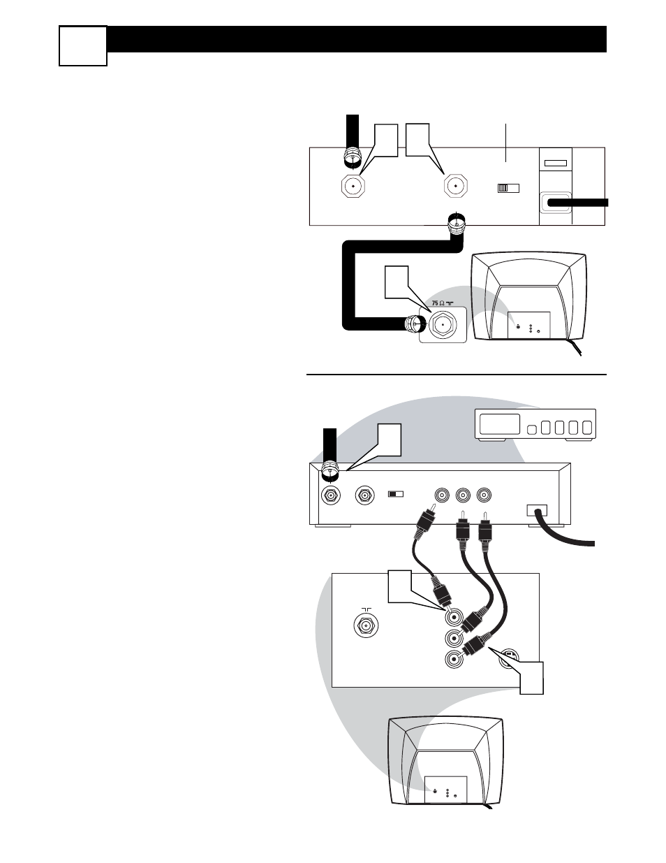
Cable Box (w/RF In/Outputs):
This connection will be mono.
1
Connect the Cable Company sup-
plied cable to the signal IN(put) plug
on the back of the Cable Box.
2
Using a separate round coaxial cable,
connect one end to the OUT(put)
(TO TV) plug on the back of the
Cable Box.
3
Connect the other end of the round
coaxial cable to the 75
Ω input on the
back of the television. Screw it down
finger tight.
NOTE: Set the OUTPUT CHANNEL
SWITCH on the back of the cable box to
CH 3 or 4. Tune the TV to the same channel
and change channels at the cable box.
Cable Box (w/Audio/Video Outputs):
This connection will supply Stereo sound.
4
Connect the Cable Company sup-
plied cable to the cable signal
IN(put) plug on the back of the Cable
Box.
5
Using a RCA type Video Cable, con-
nect one end of the cable to the
Video (or ANT, your cable box may be
labeled differently) Out jack on the
cable box and the other end to the AV1
Video Input on the TV.
6
Connect one end of the Audio Left
and Right Cable to the left and right
Audio Out L & R jacks on the cable
box. Connect the other end to the AV1
Audio L & R Input jacks on the TV.
NOTE: Use the Channel +, or – buttons on
the TV remote control to tune to the AV1
channel for the cable box signal. Once
tuned, change channels at the cable box, not
the television.
75
⍀
VIDEO
L
AUDIO
R
AV1
in
S-VIDEO
CABLE
IN
TO
TV
VIDEO
OUT
L
R
AUDIO
OUT
3 4
OUTPUT
CH
TO TV
CABLE
IN
3
1 2
4
5
6
OUTPUT
CH
3 4
24
75
⍀
VIDEO
L
AUDIO
R
AV1
in
S-VIDEO
75
⍀
VIDEO
L
AUDIO
R
AV1
in
S-VIDEO
Jack Panel Back of Cable Box
Cable Signal IN
from the Cable
Company
Round 75
Ω
Coaxial Cable
Jack Panel Back of TV
Cable Signal IN
from the Cable
Company
Cable Box with A/V Outputs
Jack Panel
Back of TV
Audio Cables
L & R (Red, White)
Video Cable (Yellow)
Output Channel Switch
Cable Box (w/RF In/Outputs):
Cable Box (w/Audio/Video Outputs):