Product, Views – Philips 200P6ES-27 User Manual
Page 10
Product Information
3
T.M.D.S. Data2
Shield
11
T.M.D.S. Data1
Shield
19
T.M.D.S. Data0
Shield
C3
* Analog B
4
NC
12
NC
20
NC
C4
* Analog H-sync
5
NC
13
NC
21
NC
C5
* Analog GND
(Analog R, G, B
return)
6
DDC Clock
14
+5V
22
T.M.D.S. Clock
Shield
7
DDC Data
15
Ground (return for
+5V and H/V-sync)
23
T.M.D.S. Clock+
8
* Analog V-sync
16
Hot Plug Detect
24
T.M.D.S. Clock-
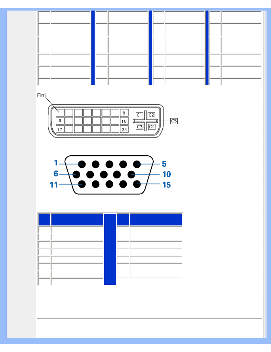
2. The 15-pin D-sub connector (male) of the signal cable:
Pin
No.
Assignment
Pin
No.
Assignment
1
Red video input
9
+5V
2
Green video input/SOG
10
Ground
3
Blue video input
11
Ground
4
Ground
12
Serial data line (SDA)
5
Cable detect
13
H. Sync / H+V
6
Red video ground
14
V. Sync (VCLK for DDC)
7
Green video ground
15
Data clock line (SCL)
8
Blue video ground
Product Views
file:///D|/My%20Documents/dfu/200P6/english/200P6/product/product.htm (5 of 9)2006-01-05 12:24:50 PM