Bard WH183 User Manual
Page 14
Manual 2100-373
Page 12
HEAT ANTICIPATION
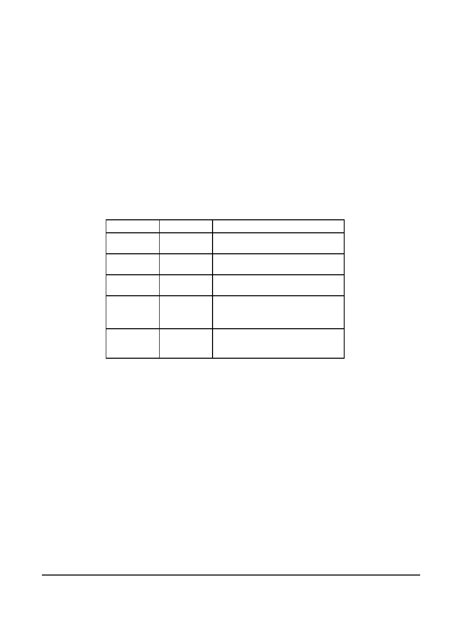
Group A and Group B thermostats shown in Table 4
have a fixed heat anticipator for stage 1 with no
adjustment required. Stage 2 has an adjustable
anticipator for the W2 connection and fixed for the W3
connection. Both the W2 and W3 circuits are
controlled by the stage 2 bulb. The only heat
anticipator that needs to be checked is stage 2 and it
should be set to match the load carried by the W2
circuit. The normal factory wiring provides for only
one electric heat contactor to be controlled by W2, and
the anticipator should be set at .40A. If special field
wiring is done, it is best to actually measure the load but
a good rule is .40A for each heat contactor controlled
by W2.
THERMOSTAT INDICATOR LAMPS
The green lamp marked “Check” will come on if there
is any problem that prevents the compressor from
running when it is supposed to be.
COMPRESSOR MALFUNCTION LIGHT
Actuation of the green “Check” lamp is accomplished
by a relay output from the heat pump control board
which is factory installed. Any condition such as loss
of charge, high head pressure, etc., that will prevent
compressor from operating will cause green lamp to
activate. This is a signal to the operator of the
equipment to place system in emergency heat position.
TABLE 4
WALL THERMOSTAT AND SUBBASE COMBINATIONS
t
a
t
s
o
m
r
e
h
T
e
s
a
b
b
u
S
s
e
r
u
t
a
e
F
t
n
a
n
i
m
o
d
e
r
P
5
4
0
-
3
0
4
8
)
1
6
7
1
A
1
4
8
T
(
-
-
-
b
l
u
b
y
r
u
c
r
e
M
;t
a
e
h
.
g
t
s
2
;l
o
o
c
.
g
t
s
1
r
e
v
o
e
g
n
a
h
c
l
a
u
n
a
M
7
1
0
-
3
0
4
8
)
9
2
1
1
R
4
7
8
T
(
9
0
0
-
4
0
4
8
)
1
8
1
1
L
4
7
6
Q
(
b
l
u
b
y
r
u
c
r
e
M
;t
a
e
h
.
g
t
s
2
;l
o
o
c
.
g
t
s
2
r
e
v
o
e
g
n
a
h
c
l
a
u
n
a
M
8
1
0
-
3
0
4
8
)
4
2
0
1
N
4
7
8
T
(
0
1
0
-
4
0
4
8
)
1
6
2
1
F
4
7
6
Q
(
b
l
u
b
y
r
u
c
r
e
M
;t
a
e
h
.
g
t
s
2
;l
o
o
c
.
g
t
s
2
r
e
v
o
e
g
n
a
h
c
l
a
u
n
a
M
r
o
o
t
u
A
2
4
0
-
3
0
4
8
)
0
7
0
1
G
1
1
5
8
T
(
-
-
-
t
a
e
h
.
g
t
s
2
;l
o
o
c
.
g
t
s
1
e
l
b
a
m
m
a
r
g
o
r
P
-
n
o
N
c
i
n
o
r
t
c
e
l
E
r
e
v
o
e
g
n
a
h
c
l
a
u
n
a
M
r
o
o
t
u
A
9
4
0
-
3
0
4
8
)
0
8
3
-
3
9
F
1
(
-
-
-
t
a
e
h
.
g
t
s
3
;l
o
o
c
.
g
t
s
2
c
i
n
o
r
t
c
e
l
E
e
l
b
a
m
m
a
r
g
o
r
P
r
e
v
o
e
g
n
a
h
c
l
a
u
n
a
M
r
o
o
t
u
A
IMPORTANT NOTE: The thermostat and subbase combinations shown
above incorporate the following features: Man-Auto fan switch,
Off-Heat-Cool-Em. Heat Switch, and two (2) indicator lamps;
one for emergency heat and one for compressor malfunction.