Electrical requirements, Plumbing requirements, Initial set-up – Bunn TWF User Manual
Page 4
Page 4
ELECTRICAL REQUIREMENTS
CAUTION - The brewer must be disconnected from the power source until specified in
Initial Set-Up.
120V model brewers require 2-wire, grounded service rated 120 volt
ac, 15 amp, single phase, 60 Hz.
120/208V model brewers require 3-wire, grounded service rated 120/
208 volt, 20 amp, single phase, 60 Hz.
Electrical Hook-Up
CAUTION – Improper electrical installation will damage electronic components.
1. An electrician must provide electrical service as specified.
2. Remove the top lid and rotate the control thermostat knob fully counterclockwise to the "OFF" position.
3. a) 120V brewers have an attached cordset. Plug in the brewer and proceed to #6.
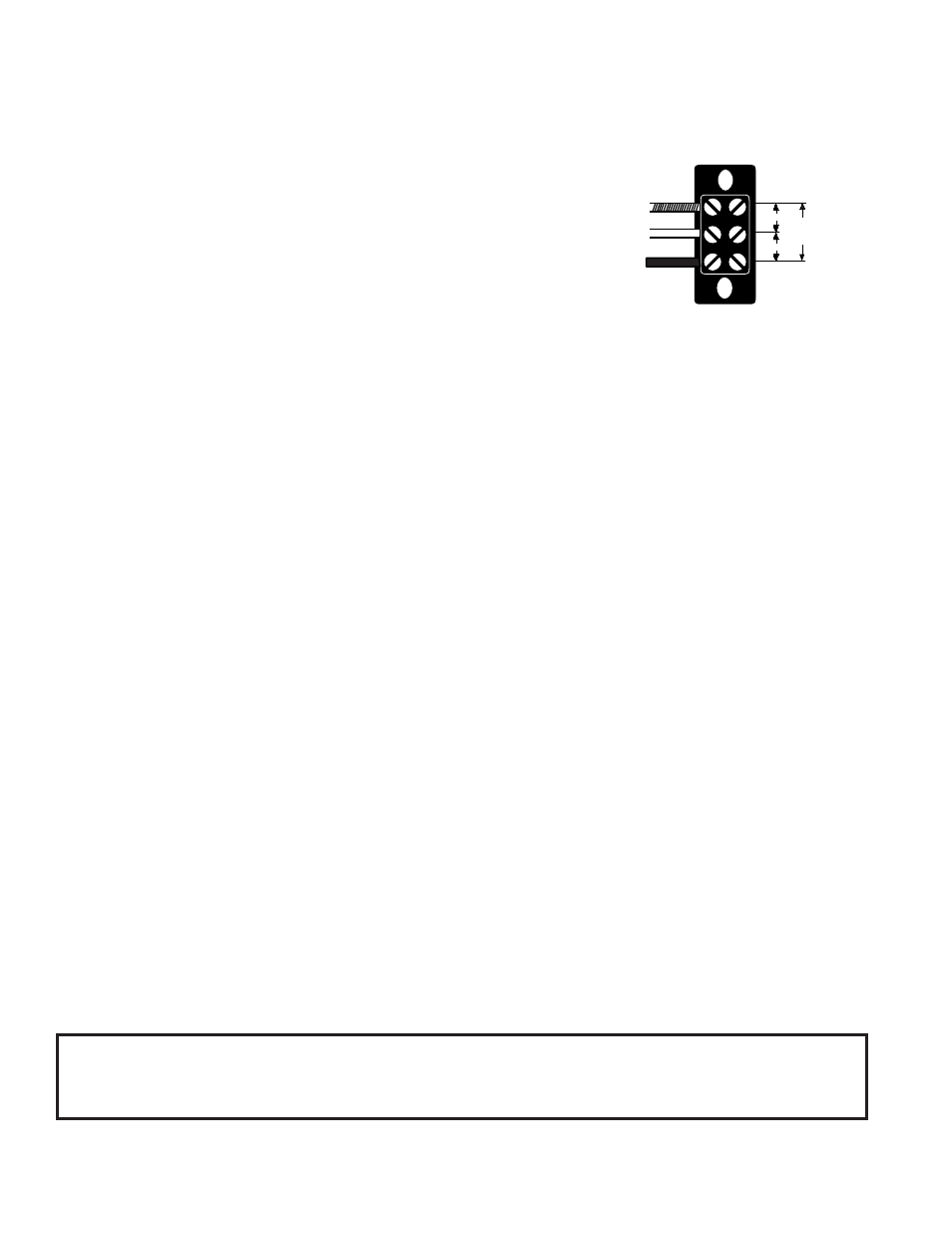
b) 120/208V brewers, feed the cord through the strain relief at the rear of the brewer and connect it to the
terminal block.
4. Using a voltmeter, check the voltage and color coding of each conductor at the power source.
5. Connect the brewer to the power source and verify the voltage at the terminal block.
6. If plumbing is to be hooked up later be sure the brewer is disconnected from the power source. If plumbing
has been hooked up, the brewer is ready for
Initial Set-Up.
PLUMBING REQUIREMENTS
These brewers must be connected to a cold water system with operating pressure between 20 (128) and 90
psi (620 kPa) from a
1
⁄
2
" or larger supply line. A shut-off valve should be installed in the line before the brewer.
Install a regulator in the line when pressure is greater than 90 psi (620 kPa) to reduce it to 50 psi (345 kPa). The
water inlet fitting is
1
⁄
4
" flare.
NOTE - Bunn-O-Matic recommends
1
⁄
4
" copper tubing for installations of less than 25 feet and
3
⁄
8
" for more than
25 feet from the
1
⁄
2
" water supply line. A tight coil of copper tubing in the water line will facilitate moving the
brewer to clean the countertop. Bunn-O-Matic does not recommend the use of a saddle valve to install the
brewer. The size and shape of the hole made in the supply line by this type of device may restrict water flow.
1. Remove the shipping cap(s) from the bulkhead fitting(s) on the rear of the brewer.
2. Attach the flare fitting from the short piece of tubing on the strainer/flow control (supplied) to the water inlet
fitting(s) at the rear of the brewer.
3. Flush the water line and securely attach it to the flare fitting on the tee or strainer/flow control.
4. Turn on the water supply.
5. On brewers with a faucet, place an empty vessel beneath the faucet and lift the handle until water is dis-
pensed.
L2 RED
WHITE
NEUTRAL
L1 BLACK
120V.A.C.
120V.A.C.
208V.A.C.
This equipment must be installed to comply with the Basic Plumbing Code of the
Building Officials and Code Administrators International, Inc. (BOCA)
and the Food Service Sanitation Manual of the Food and Drug Administration (FDA).
10510 071000