Fonctions et commandes, Features and controls – Briggs & Stratton Air Compressor User Manual
Page 8
8
BRIGGSandSTRATTON.COM
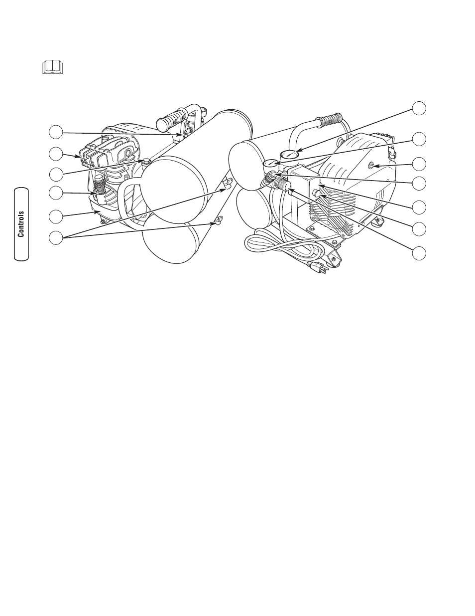
Features and Controls
Read this Operator’s Manual and safety rules before operating your air compressor.
Compare the illustrations with your air compressor, to familiarize yourself with the locations of various controls and
adjustments. Save this manual for future reference.
A - Safety Valve — Valve protects against excessive tank
pressure by ‘popping out’ at its factory setting, thus
relieving pressure.
B - Air Filter — Protects air compressor by filtering dust
and debris out of intake air.
C - Check Valve — When unit is operating, check valve is
open, allowing air to enter tank. At “cut-out” pressure,
check valve closes, preventing air from flowing back into
pump. Valve is not serviceable by user.
D - Oil Dipstick — Remove to check and add compressor
pump oil.
E - Air Compressor Pump — Pump compresses air into
tank.
F - Drain Valves — Valves are located near bottom of each
air tank and is used to drain condensation.
G - Pressure Control — Controls air pressure delivered to
Quick Connect Fitting; can be secured with locking ring.
H - ON - OFF Switch — Pull to ON position to power air
compressor. Push to OFF position to remove power.
J - Pressure Switch — Automatically starts motor when tank
pressure drops below “cut-in” pressure and stops motor
when pressure rises to “cut-out” pressure.
K - Quick Connect Fitting — Connect air tools here.
L - Overload Protector — If motor is overloaded, protector
shuts motor off. See Overload Protection Reset.
M - Regulated Pressure Gauge — Indicates air pressure at
quick connect fitting.
N - Tank Pressure Gauge — Gauge indicates air pressure
within air tank.
Items Not Illustrated:
Data Tag: The data tag contains serial number, model
number, and revision number information.
Pressure Release Valve: Located on top of tank adjacent to
quick connect fitting, valve automatically releases air from
internal compressor components at “cut-out” pressure or
when unit is shut off. Valve is not serviceable by user.
NOTE: See Glossary for definitions.
A
K
H
B
N
E
M
C
J
G
F
L
D