1installing the appliance, Putting into operation – Liebherr WTEes 2053 Vinidor User Manual
Page 7
q
Torx screwdriver 15
q
Torx screwdriver 25
q
Torx screwdriver 30
q
Spanner
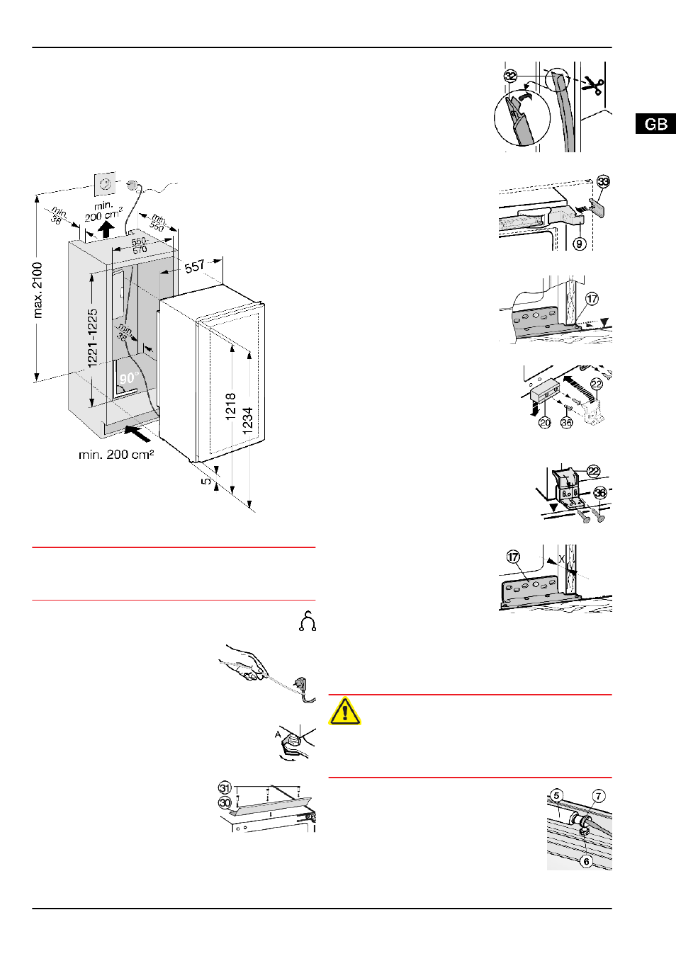
The shelf and side walls of the unit must be at right-angles to
one another. Align the unit with a spirit level and an angle. If
necessary, level out by building up from underneath.
Check installation dimensions:
Fig. 22
4.4.1 Installing the appliance
NOTICE
Risk of damage to the door!
u
Detach door transit supports only when the appliance is slid
fully into the recess.
u
Detach the connecting cable from the rear of the appli-
ance, removing the cable holder because otherwise
there will be vibratory noise!
u
Lay the connecting cable with
the help of a string in such a way
that the appliance can be easily
connected after fitting.
u
Slide the appliance 2/3 of the
way into the recess.
Fig. 23
u
Turn in the adjustable-height feet all the way.
u
Fix
the
equaliser
trim
Fig. 24 (30)
with screws
Fig. 24 (31)
in the pilot holes
in the ceiling of the appliance.
Fig. 24
u
Strip the protective film off
the cover trim
Fig. 25 (32)
.
u
Adhesively affix the cover
trim
Fig. 25 (32)
on the
handle side so as to be
flush with the front of the
side wall of the appliance.
u
If necessary, shorten the
cover trim to recess height.
Fig. 25
For 16 mm thick unit walls
(568 mm wide recess):
u
Press spacer
Fig. 26 (33)
onto
the
turn
hinge
Fig. 26 (9)
in the area of the
slot.
For 19 mm thick unit walls
(562 mm wide recess):
u
the spacer is not needed.
Fig. 26
u
Push the appliance into the
recess until the lower turn
hinge
Fig. 27 (17)
abuts the
end face of the unit wall.
w
The turn hinge
Fig. 27 (17)
bears on the floor of the
recess.
Fig. 27
u
Detach the
Fig. 28 (20)
transit
support.
If the appliance is transported
again, the transit support has to
be re-fitted:
Fig. 28
u
Do not dispose of the transit support for the door.
u
Screw plastic bracket
Fig. 29 (22)
onto the handle side of the appli-
ance with M5 screws
Fig. 29 (36)
.
u
Align the plastic bracket
Fig. 29 (22)
so as to be flush with the front edge
of the unit floor.
Fig. 29
u
At the bottom of the turn hinge
Fig. 30 (17)
, measure the
distance (X) from the front
edge of the unit side wall to the
appliance.
u
Check whether the measure-
ment made is the same all the
way round, otherwise the door
may not close properly.
u
If necessary, extend the adjust-
able-height foot on the handle
side so as to make up for any
unevenness of the floor.
Fig. 30
CAUTION
Danger of injury by the soft stop mechanism!
If the soft stop mechanism contracts and strikes the appliance,
fingers may get caught and the appliance may be damaged.
u
Keep a firm hold on the soft stop mechanism.
u
Lift the soft stop mechanism
Fig. 31 (5)
off the ball journal
Fig. 31 (6)
. Carefully lift the spring
using a screwdriver in order to detach
the spring clip
Fig. 31 (7)
.
u
Carefully swivel the soft stop mecha-
nism to the appliance.
Fig. 31
Putting into operation
7