Pinpoint mode – Bounty Hunter DISCOVERY 3300 User Manual
Page 5
5
ASSEMBLY
20
IN THE FIELD TECHNIQUES
- Pinpoint Mode
GROUND BALANCING
Before using the PINPOINT mode, it is necessary to ‘Ground Balance” your
detector, this ground balancing adjustment offsets the effects of minerals and
slats in the ground.
To GROUND BALANCE your detector:
1. Using the ALL-METAL mode, find a patch of ground which is free of metal
objects. You will use this section of ground to test the detector. The presence
of any metal objects in this area will interfere with this procedure.
2. Begin with the ground balance KNOB in the
PRESET position.
3. Lift the search coil waist
high in the air.
4. Press the PINPOINT touch pad.
5. Lower the searchcoil to
the ground, maintaining it
elevated about 1/2 inch
above the surface (be sure
that this ground does not contain metal).
• If the detector emits sound with the searchcoils 1/2 inch
over the ground, further
ADJUSTMENT IS NECESSARY.
• If the detector remains silent with the searchcoil 1/2 inch
over the ground, no further adjustment is necessary; the detector is
“GROUND BALANCED”
6. If the detector emits sound with the coil over the ground in STEP 5, further
adjustment of the ground balance KNOB is required as follows:
•
Lift the searchcoil waist high
•
Rotate the ground balance KNOB clockwise 1/16 of a turn
•
Press PINPOINT
•
Lower the searchcoil to the ground again
If the detector still emits a tone, repeat the procedure. You are searching for the
ground balance knob positiion where the detector is
just silent.
It is important to move the knob in small increments in order to find the first
setting (moving clockwise) at which the detector remains silent. To insure
yourself of the optimal adjustment, move the KNOB slightly counterclock-
wise from a silent-adjusted position to check for the
most counterclockwise
silent position possible.
If the KNOB is over-adjusted in the clockwise direction, the detector can lose
sensitivity. An over-adjusted condition can also cause the detector to sound
off when the coil is lifted away from the ground.
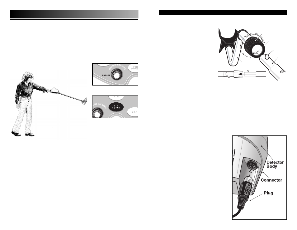
Assembly is easy and requires no tools.
●
1
Position detector upright.
●
2
Rotate the LOCKING
COLLAR fully in a counter
clockwise direction.
●
3
Insert your finger inside the
tube and make sure the
INTERNAL CAM LOCK is
flush with the inside of the
tube.
●
4
Insert the LOWER STEM into
the S-ROD.
●
5
Rotate the LOWER STEM until the SILVER BUTTON locates in the hole.
●
6
Twist the LOCKING COLLAR fully in the clockwise direction until it locks.
●
7
If your detector has 3 tubes and 2 locking collars, repeat this process
on the Middle Stem.
●
8
Position the Lower Stem (the straight tube) with the Silver Button
toward the back. Using the Bolt and Knurled Knob, attach the
Searchcoil to the plastic extension protruding from the Lower Stem.
●
9
Press the button on the upper end of the Lower Stem, and slide the
Lower Stem into the S-Rod.
Adjust the Stem to a length that lets
you maintain a comfortable upright
posture, with your arm relaxed at
your side, and the Searchcoil parallel
to the ground in front of you.
●
10
Wind the Cable securely around the
Stem.
●
11
Insert the Plug into the matching
Connector on the right underside of
the Detector Body. Be sure that the
key-way and pins line up correctly.
Caution:
Do not force the plug in. Excess
force will cause damage.
To disconnect the cable, pull on
the plug.
Do not pull on the cable.
S-ROD
LOCKING
COLLAR
INTERNAL
CAM LOCK
SILVER BUTTON
MIDDLE
STEM
S-ROD
MIDDLE STEM