Installation, Terminal connections, M3ldy – M-System M3LDY User Manual
Page 2
M3LDY
EM-2664 Rev.2
P. 2 / 6
■
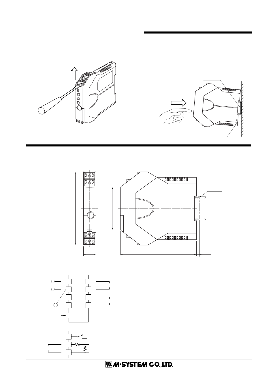
HOW TO SEPARATE THE TERMINAL BLOCKS
When you need to separate the terminal blocks from the
transmitter body for wiring, insert a minus driver between
the terminal block and the housing body, pull up the driver
and pull out the terminal block.
DIN Rail
35mm wide
Spring Loaded
DIN Rail Adaptor
INSTALLATION
■
DIN RAIL MOUNTING
Set the unit so that its DIN rail adaptor is at the bottom.
Position the upper hook at the rear side of the unit on the DIN
rail and push in the lower. When removing the unit, push
down the DIN rail adaptor utilizing a minus screwdriver and
pull.
TERMINAL CONNECTIONS
Connect the unit by referring to the diagram below.
■
EXTERNAL DIMENSIONS mm (inch)
10 11 12
7
8
9
4
5
6
1
2
3
106 (4.17)
18 (.71)
110.5 (4.35)
62 (2.44)
[3.3 (.13)]
¥When mounting, no extra space is needed between units.
35.4 (1.39)
DIN RAIL
35mm wide
■
CONNECTION DIAGRAM
+
–
+
–
4
CONFIGURATOR
JACK
7
8
11
12
OUTPUT
POWER
+
–
1
3
2
2-WIRE
TRANSMITTER
+
–
V
–
+
(1 – 5VDC)
MONITOR
24.9
Ω
250
Ω
+
No Connection
–
INPUT
2
1
3
■
When Used as Isolator