Sensor hookup diagrams for ma3-4 micro-amp modules, Beam pattern, Excess gain models/dimensions beam pattern – Banner MA3-4 User Manual
Page 5: Fiber optic mode
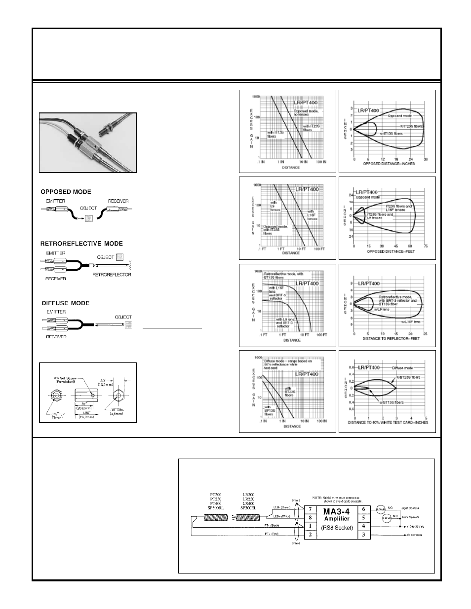
FIBER OPTIC Mode
glass fiber optics
The threaded barrel design of the
LR400 and PT400 permit the con-
nection of any Banner glass fiber
optic assembly by using two model
FOF-400 fittings. The sensors are
typically mounted through a 3/8
inch (10mm) diameter clearance
hole, with the FOF-400 fittings
threaded onto them after mount-
ing. Setscrews in the fittings lock
the fibers in place, but allow rapid
replacement without disturbing any
electrical wiring.
As the excess gain curves show, the
LR/PT400 combination produces a
high-performance fiber optic sens-
ing system. With the amplifier's
1 millisecond response time, this
system can be used for almost any
fiber optic requirement.
Range: see excess gain curves
Temp. range: -40 to +100°C
LR400 & PT400
with FOF-400 fittings
and fiber optics
The following hookup diagrams include all of the
remote sensors for use with the model MA3-4
modulated amplifier module. It is important to
note how the shield wire of a remote sensor is
wired. The shield wire is the uninsulated wire
in each sensor cable. Failure to connect the
shield as shown may result in false operation of
the amplifier. When wiring emitters, it is good
practice to connect the positive wire first. LEDs
are sensitive to application of the wrong voltage,
and can easily be destroyed.
NOTE: only one sensor may be connected to
each MA3-4 amplifier.
Sensor Hookup Diagrams for MA3-4 MICRO-AMP Modules
(continued on
page 6)
NOTE: Shield wires must be connected as shown to avoid cable crosstalk.
Hookup of LR/PT200, 250, 300, and 400
Beam Pattern
5
Sensors for use with MA3-4 and MA3-4P Modulated Amplifiers
Sensors are epoxy-encapsulated and optics are hermetically sealed. Cables are 6-1/2 feet (2m) long. 30-foot (9m) cables available by special
order.
Excess Gain
Models/Dimensions
Beam Pattern
Fiber optic information:
IT13S: individual assembly .06 in.
(1,5mm) dia. bundle
IT23S: individual assembly .12 in.
(3mm) dia. bundle
BT13S:bifurcated assembly .06 in.
(1,5mm) dia. bundle
BT23S:bifurcated assembly .12 in.
(3mm) dia. bundle
L9: .5 in. (12mm) dia. lens
L16F: 1.0 in. (25mm) dia. lens
FOF-400 fiber optic fitting